
Method for measuring pulse signal period

A pulse signal and period measurement technology, applied in the direction of frequency measurement device, frequency to pulse sequence conversion, etc., can solve the problem of pulse period measurement error and other problems, and achieve the effect of eliminating competition

Inactive Publication Date: 2011-07-20
SHANGHAI UNIV
View PDF7 Cites 17 Cited by
  • Summary
  • Abstract
  • Description
  • Claims
  • Application Information

AI Technical Summary

Problems solved by technology

Because the traditional periodic method needs two interrupts, edge and overflow, when the pulse edge interrupt and count overflow interrupt occur at the same time, interrupt competition will occur, which will cause errors in the measured value of the pulse period.

Method used


Image

  • Method for measuring pulse signal period
  • Method for measuring pulse signal period
  • Method for measuring pulse signal period

Examples


Embodiment Construction

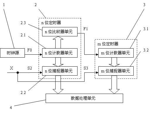
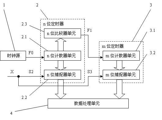
[0014] A preferred embodiment of the present invention is as follows: see figure 1 . A method for measuring the period of a pulse signal, using a clock source 1, an n-bit timer 2, an m-bit timer 3 and a data processing unit 4; the n-bit timer 2 has an n-bit counter unit 2.1 and n-bit capture Device unit 2.2 and n-bit comparator unit 2.3, m-bit timer 3 has m-bit counter unit 3.1 and m-bit catcher unit 3.2; n-bit catcher unit 2.2 of n-bit timer 2 rises to input terminal S2 pulse (or The count value of the n-bit counter unit 2.1 corresponding to the time of the instant of the falling) edge change is captured, and the m-bit capture unit 3.2 of the m-bit timer 3 corresponds to the time of the rising (or falling) edge of the input terminal S3 pulse. The count value of the bit counter unit 3.1 is captured; the captured values ​​of the n-bit capture unit 2.2 and the m-bit capture unit 3.2 are sent to the data processing unit 4 . It is characterized in that clock source 1 outputs fre...


PUM


Abstract

The invention provides a method for measuring pulse signal period. The method comprises the following steps of: using hardware functions of a comparator unit and a catcher unit in a timer of a current single-chip microprocessor; using a working lock with relative high frequency FO for a n-bit timer; using a n-bit counter overflow pulse in the timer as the working clock of the counter in another m-bit timer; simultaneously accessing pulse signals to be measured into an input end of the catchers in the two timers so that two catchers can simultaneously catch the corresponding time values under the triggering of the edge of the pulse signal X so as to obtain the time value of one working clock with frequency of FO and a high-order time value of another working clock with frequency F1=F0 / 2n, namely obtaining a time catching value with a wide range. Therefore, the method in the invention solves the time-competitive problem of program response of counting overflow interruption and edge catching interruption. The catcher hardware is directly used for obtaining the pulse edge time with the wide range and high precision so as to obtain the pulse period value with wide range and high precision via the difference value of the two pulse edge time catching values.

Description

technical field [0001] The invention relates to a method for measuring the period of a pulse signal, in particular to a method for measuring the period of a pulse signal with a particularly large period variation range. Background technique [0002] Pulse signal is a signal form that is widely used in sensors and detection instruments. There are already quite mature technologies for the period measurement of relatively stable pulse signals. However, when the pulse signal has a large variation range and is mixed with interference pulses, it is often necessary to accurately measure the period of each input pulse, so that statistical methods such as removing the maximum and minimum period values ​​can be used to accurately estimate the period of the pulse signal. At the same time, many pulse signals to be measured have a particularly large period range. For example, the pulse period change of a 15mm~600mm caliber sensor in a vortex flowmeter (corresponding to a pulse frequency...

Claims


Application Information

Patent Timeline
IPC IPC(8): G01R23/10
Inventor 沈天飞李斌尹仕熠周平雨李伟
Owner SHANGHAI UNIV
Learn More