
Method and sensor for detecting relative sliding velocity between plate and mould in stamping process

A technology of relative sliding and sliding speed, which is applied in the direction of devices using optical methods, can solve the problems of methods and sensors without sliding speed, and is not suitable for stamping and forming of sheet metal, so as to achieve strong anti-multipath effect, reduce interference, Ease of installation and removal

Active Publication Date: 2011-07-20
BAOSHAN IRON & STEEL CO LTD
View PDF0 Cites 4 Cited by
  • Summary
  • Abstract
  • Description
  • Claims
  • Application Information

AI Technical Summary

Problems solved by technology

[0012] However, after reviewing the prior art, many of the above-mentioned methods including the image measurement method are aimed at detecting the moving speed of the vehicle, and there are no methods and sensors for the sliding speed; in addition, the previous detection methods and installation methods are Not suitable for sheet metal stamping and forming processes

Method used


Image

  • Method and sensor for detecting relative sliding velocity between plate and mould in stamping process
  • Method and sensor for detecting relative sliding velocity between plate and mould in stamping process
  • Method and sensor for detecting relative sliding velocity between plate and mould in stamping process

Examples


Embodiment 1

[0061] The sliding speed sensor is installed on the universal plate formability testing machine for deep drawing test detection, and the sliding speed of the flange part is detected during the deep drawing process.

[0062] First, put the detection sensor into the die, install the die on the test bench, then connect the detection sensor to the control box, and use the computer serial port to connect the control box to the computer (CPU). At the same time, connect the control box Power supply 16 ensures that the control box works. Drawing die and detection sensor installation holes such as Figure 7 As shown, the system is connected as shown in Figures 8 and 9.

[0063] The detection sensor includes a main control unit (MCU) 5, a laser displacement detection unit 12 connected to the main control unit (MCU) telecommunication, and the main control unit (MCU) includes a communication module 2 connected by telecommunication, a storage module 1, An adaptive optimization module 4 a...


PUM


Abstract

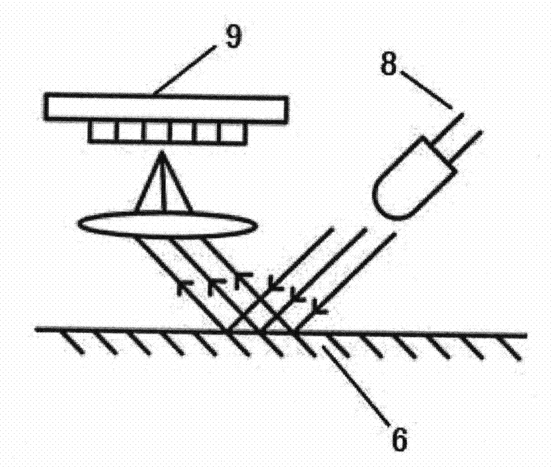
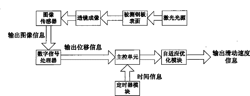
The invention relates to a method and a sensor for detecting the relative sliding velocity between a plate and a mould in a stamping process. The method comprises the following steps of: (1) forming an area measured laser image on the measured surface of a steel plate; (2) acquiring the image information of continuously changed patterns and outputting the image information to a signal processor by using an image sensor; (3) analyzing the movement amount of a characteristic area by adopting a self-correlation image processing algorithm, and outputting displacement information; (4) outputting sliding velocity data by using a master control unit; (5) adjusting an acquisition frequency by using the master control unit; (6) obtaining a conversion function for a sliding velocity value and sliding velocity data: y=ax+b; and (7) obtaining an actual relative sliding velocity. By using the detection method and the sensor, the sliding velocity can be measured in a real-time and non-contact way in a plate stamping process. The method has high operability and can be used for determining the sliding velocity of the steel plate relative to the mould in plate stamping deformation by matching a corresponding test device, thereby meeting requirements on scientific research and test.

Description

Technical field: [0001] The present invention relates to the field of speed detection. Specifically, the present invention relates to a method for detecting the relative sliding speed of a plate and a mold and a sensor used therefor. More specifically, the present invention relates to a relative sliding speed of a plate and a mold in stamping forming. detection methods and sensors. The detection method and the sensor of the invention can be used for detecting the sliding speed of the plate relative to the surface of the mold during the stamping process of the plate. Background technique [0002] In the sheet metal stamping forming process, especially in the steel plate stamping forming process, the sliding speed of the steel plate relative to the die is an important parameter affecting the friction and contact state. The friction coefficient between the steel plate and the die has different friction coefficients under different sliding speeds, and Exhibit different friction...

Claims


Application Information

Patent Timeline
Patent Type & Authority Applications(China)
IPC IPC(8): G01P3/36
Inventor 刁可山陈新平蒋浩民
Owner BAOSHAN IRON & STEEL CO LTD
Learn More