
Method for grouting floor slab bushing hole reservation preembedding die and grouting die

A construction method and casing technology, applied in the direction of formwork/formwork/work frame, pipe, pipe/pipe joint/pipe fitting, etc., can solve the problems of water leakage, large chisel area, poor force, etc., to avoid dislocation The effect of excessive error, accurate installation position and small operation error

Active Publication Date: 2013-01-09
湖南省第五工程有限公司 +1
View PDF5 Cites 0 Cited by
  • Summary
  • Abstract
  • Description
  • Claims
  • Application Information

AI Technical Summary

Problems solved by technology

[0003]1. When installing risers in multi-storey buildings, since the reserved holes and casing installation are carried out step by step, the existing reserved holes On the basis of the casing, the casing is installed, and the positioning method of the reserved hole during the construction process is determined only by the experience of the construction personnel. The positioning reference is not determined, and the pre-buried position of the hole is not accurately positioned. The size of the hole Only a rough estimate is made, which inevitably leads to inaccurate positions and axial center deviations of the reserved holes for construction between floors, which may easily lead to inaccurate positions and sizes of reserved and pre-buried holes for floor casings. When the pipe is installed, the upper and lower risers cannot be connected and installed. It is necessary to correct the reserved opening first. Usually, it is necessary to repair the holes on multi-storey floors. Some local locations may need to be repaired repeatedly.
If the standpipe and the floor casing are installed together, it is inevitable to perform secondary grouting and stabilize the casing operation, the construction efficiency is low, the labor time is more, and the quality problems often occur during the installation process
[0004] 2. Since the construction of the reserved holes is not organically combined with the construction of the floor slab to accurately locate the position and size of the holes, the displacement of the pre-buried holes in the casings on each floor is too large , the repairing area is large, and it is difficult to fill the hole. The hole filling construction usually needs to be sealed with a formwork. However, in the prior art, there is no mold specially used for the grouting construction of the floor casing hole, and only temporary formwork is used to seal it. This temporary support method is not well stressed during the pouring process. When the force is added during the pouring process, the formwork is prone to instability, causing the concrete slurry to fall or even to be exposed. Second repairs must be carried out, and this repair Chiseling work The construction work is usually not suitable for the pipeline construction set in the corner of the wall, but most of the risers are usually set in the corner of the wall, which does not provide a repair chisel work space, can not be repaired chiseling, adds new quality problems, and even affects the construction quality and Perceptual acceptance
[0005]3. Due to the need to use the water stop ring, it will be damaged due to improper installation position or improper concrete construction method during use, which will easily cause water leakage, and For the waterproof casing with a water stop ring, the relevant installation regulations do not allow the post-pouring method, and it can only be remedial measures.
[0006]4. Micro-expansion fine stone concrete with higher strength must be used for pouring, while ordinary floor casings generally only use fine stone concrete with the same strength as the floor Perfusion is enough, increasing the cost

Method used


Image

  • Method for grouting floor slab bushing hole reservation preembedding die and grouting die
  • Method for grouting floor slab bushing hole reservation preembedding die and grouting die
  • Method for grouting floor slab bushing hole reservation preembedding die and grouting die

Examples


Embodiment 1

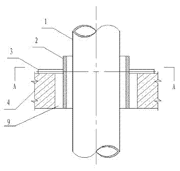
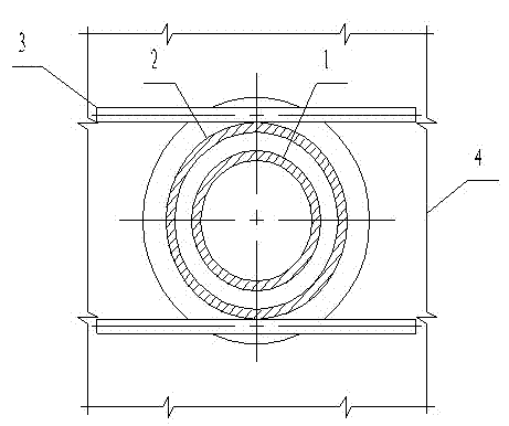
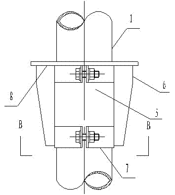
[0043] Pre-embedded grouting molds are reserved for floor casing holes, such as Figure 1 to Figure 5As shown, its structure is as follows: it is composed of a clamping cylinder body 5 and a plane template 8 fixed on the top of the clamping cylinder body. The clamping cylinder body 5 is an arc-shaped plate bent from a thin plate with a thickness S of 3 mm, including a combination The two standpipe wrapping plates forming a hollow cylinder and the snap ring connecting piece that fixes the two standpipe wrapping plates with open and close clamps, the snap ring link is the open and close snap ring 7, and the plane formwork on the top of the clamping mold cylinder 8 is made of a steel plate with a thickness S of 4mm according to the required size, including two flat formworks that are respectively fixed on the two riser wrapping plates and seamlessly spliced ​​together. The flat steel plate of 40×4mm is used as the bottom of the plane formwork 8. The oblique support plate 6 reinfo...


PUM


Abstract

The invention relates to a method for grouting a floor slab bushing hole reservation preembedding die and a die thereof. The method comprises the following steps of: (1) positioning a hole before the concrete casting construction of a floor slab; (2) preserving a hole during the concrete casting construction of the floor slab; (3) mounting a vertical tube in the preserved hole and primarily mounting a bushing; and (4) fixing the bushing on the floor slab and plugging a gap between the bushing and the vertical tube. The die comprises a snap gauge cylinder and a planar template fixed at the topof the snap gauge cylinder, and an inclined bracing plate fixed at a wrapping plate of the vertical tube is arranged below the planar template. The invention solves the problem of die supporting and fixing in hole grouting, the provided planar template can be favorably attached with the bottom surface of the floor slab so that the hole is compactly sealed, and the mounting quality and the requirements of use functions are ensured. The invention can improve work efficacy, ensure construction quality, reduce reworking and, ensure that the pipeline and the bushing are vertically and straightly mounted without barriers or bending and with even and straight verticality and has the advantages of convenience in operation, stability, rapidness and cost saving.

Description

technical field [0001] The invention relates to a building construction method and a mould, in particular to a grouting method for pre-embedded moulds, which can be widely used in the installation of indoor riser pipeline floor slabs. Background technique [0002] At present, the installation method commonly used in the indoor riser pipes of high-rise buildings in the prior art is to reserve and embed ordinary casing holes on the floor first, and then install the risers. For example, Chinese patent application 200810231783.9 discloses a construction project The construction method of the reserved hole on the floor, which includes cleaning the hole edge, installing the casing, installing the bottom form, pouring shrinkage compensation concrete, water storage test, applying waterproof leveling mortar and other processes, in which a water-stop ring is installed in the middle of the casing, The water-stopping path is added, which greatly hinders the penetration of water from the...

Claims


Application Information

Patent Timeline
Patent Type & Authority Patents(China)
IPC IPC(8): E04G21/00E04G15/06F16L5/00
Inventor 熊用机叶有泉杨炳泉任宪生刘齐清肖华君王文革龙兴龚学斌刘福云
Owner 湖南省第五工程有限公司
Learn More