Improved clamp structure of band sawing machine

A band saw machine and clamp technology, applied in clamping, sawing machine device, metal sawing equipment, etc., can solve the problems of occupying operating space, lack of operation safety, and operator injury.

Inactive Publication Date: 2011-07-20
昆山合济机械有限公司
View PDF5 Cites 7 Cited by
  • Summary
  • Abstract
  • Description
  • Claims
  • Application Information

AI Technical Summary

Problems solved by technology

[0002] The band saw machine structure previously used for sawing workpieces has a base, a machine column is respectively fixed on both sides of the top surface of the base, and a sawing structure of a band saw blade is arranged on the top surface of the machine column, so that The sawing structure is used for lifting and moving on the machine column to saw the workpiece; in addition, please refer to Figure 4 As shown, the top surface of the base 60 is provided with a conveying track 70 for conveying workpieces, and two clamps 80 with appropriate spacing, which are used to c...

Method used


Image

  • Improved clamp structure of band sawing machine
  • Improved clamp structure of band sawing machine
  • Improved clamp structure of band sawing machine

Examples


Embodiment

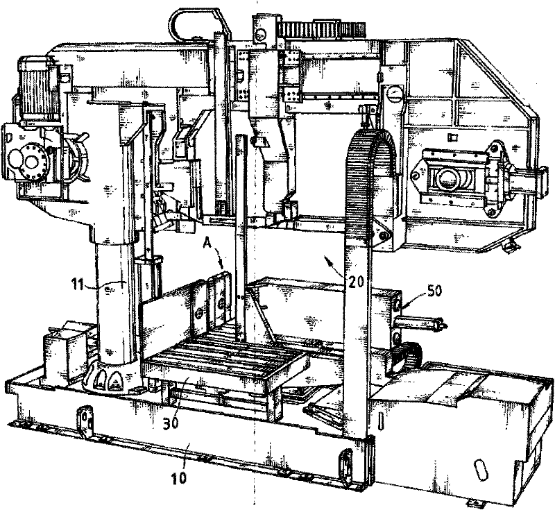
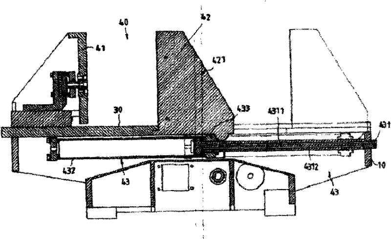
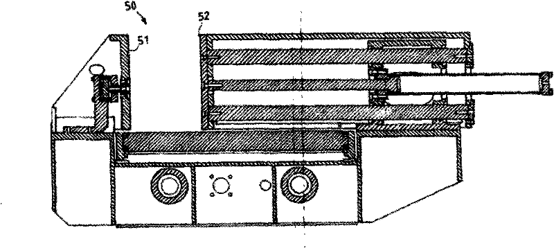
[0022] Example: First, please refer to Figure 1 to Figure 3 As shown, the present invention is an improved clamp structure of a band saw machine. The band saw machine has a base 10, a machine column 11 is fixed on the top surface of the base 10, and a machine column 11 is arranged on the top of the machine column 11. A sawing structure 20, the sawing structure 20 moves up and down with the machine column 11; in addition, the top surface of the base 10 is adjacent to the upper surface of the machine column 11, and a conveying track 30 for conveying workpieces is arranged, and the conveying track 30 A clamp structure 4 is installed at the setting position, and the clamp structure 4 has two first clamps 40 and a second clamp 50 with appropriate spacing, and the first and second clamps 40, 50 have first and second clamps respectively. The fixed clips 41,51 and the first and second movable clips 42,52, between the first and second fixed clips 41,51 and the first and second movable...


PUM


Abstract

The invention discloses an improved clamp structure of a band sawing machine. The band sawing machine is provided with a pedestal, a column is fixedly arranged at the top of the pedestal, the top of the column is movably provided with a sawing structure, and the sawing structure lifts and moves along the column; the top of the pedestal close to the column is provided with a conveying track for conveying workpieces, a clamp structure is arranged on the upper surface of the conveying track, and a clamping jaw is provided with a pressure cylinder corresponding to the lower end of the bottom surface of the conveying track; the pressure cylinder consists of a fixed cylinder rod, a movable outer pipe and a linkage block; the movable clamping part is in a concealed design form; and because the clamping jaw has small volume, the operating space is not occupied, an operator does not touch the pressure cylinder or the clamping jaw carelessly, and the operation safety is ensured.

Description

technical field [0001] The invention relates to a clamp structure, in particular to an improved clamp structure of a band saw machine. Background technique [0002] The band saw machine structure previously used for sawing workpieces has a base, a machine column is respectively fixed on both sides of the top surface of the base, and a sawing structure of a band saw blade is arranged on the top surface of the machine column, so that The sawing structure is used for lifting and moving on the machine column to saw the workpiece; in addition, please refer to Figure 4 As shown, the top surface of the base 60 is provided with a conveying track 70 for conveying workpieces, and two clamps 80 with appropriate spacing, which are used to clamp a workpiece to be sawed in the two clamps 80; The saw machine is used to use the two clamps 80 to clamp and saw the workpiece. However, because the movable part 81 and the fixed part 82 of the two clamps 80 of these band saw machines are exposed...

Claims


Application Information

Patent Timeline
IPC IPC(8): B23Q3/06B23D55/04
Inventor 赵淑佳
Owner 昆山合济机械有限公司
Why Eureka
Try Eureka