Portable shoelace tying method
A convenient, shoelace technology, applied in footwear, clothing, fasteners, etc., can solve the problems of unsafe hidden dangers, inconvenience and insecurity of children, the elderly and the disabled, and achieve the effect of reducing unsafe hidden dangers.
- Summary
- Abstract
- Description
- Claims
- Application Information
AI Technical Summary
Problems solved by technology
Method used
Image
Examples
Embodiment 1
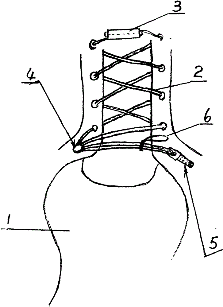
[0024] 1. Fold a single shoelace 2 half rings in half to form a double strand with two shoelace heads at one end;
[0025] 2. After the double-strand shoelace 2 bypasses the shoelace button 4, use the two shoelaces 2 ends to interweave from the back to the front eyelet;
[0026] 3. Insert and fix the two shoelace heads in the shoelace head locking sleeve 3 at the front end of the shoe, leave the half-folded part of the shoelace behind the shoelace button 4 and place it naturally, and tie a ring-shaped elastic belt near the half-folded shoelace; The elastic band can also be hung on the hook of the buckle, which is simple and convenient, and the elastic band and the shoelace half ring can be selected;
[0027] 4. Hang the double-folded part of the shoelace 2 on the hook of the buckle 5, and untie the shoelace 2 through the buckle 5.
[0028] A rotatable collar is added outside the cylinder of the shoelace button 4 so that the shoelace 2 can be pulled in the shoelace button 4 . ...
Embodiment 2
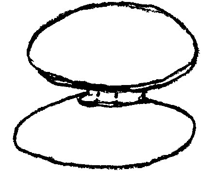
[0033] Such as Figure 6 , 7 As shown, the buckle is a snap-chain buckle, wherein 21 is a buckle cover B, 22 is a button B, 23 is a hook B, 24 is a rotating shaft, 25 is a buckle plate, 26 is a permanent magnet sucker, and 27 is a clip chain .
[0034] Injection molding one-way tooth snap chain 27, make a buckle cover B21 with sheet metal, a rotating shaft 24 is installed in the middle part of buckle cover B21, a rotatable metal gusset 25 is fixed on the rotating shaft 24, and the front end of gusset 25 has an arc-shaped tooth, The arc-shaped teeth and the clip chain 27 can be inserted and matched, and a button B22 is fixed at the end of the rotating shaft 24. The rear end of the pinch plate 25 overlaps with the permanent magnet sucker 26 up and down. The arc-shaped teeth at the front end of 25 are inserted into the clip chain 27, and the shoelaces are fixed by hanging on the hook B23. When the button B22 is turned, the pinch plate 25 breaks away from the permanent magnetic ...
Embodiment 3
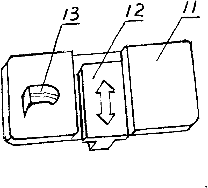
[0037] Such as Figure 8 Shown, buckle is buckle cover type buckle, and wherein, 31 is base plate, and 32 is L-shaped buckle plate, and 33 is fixing belt.
[0038] Fixed belt 33 penetrates base plate 31 and is fixed on the side of the vamp, and is provided with a rotating shaft on the short plate of L-shaped gusset 32. When the L-shaped gusset 32 is pulled by hand, the long plate of L-shaped gusset 32 will go around the shaft. When turning upturned, shoelace 2 half-rings are folded in half and hung in the long plate of L-shaped gusset 32, and the long plate of L-shaped gusset 32 is pressed downward, and fixed by the side teeth of the short plate of L-shaped gusset 32. Belt 33 bites are fixed.
[0039] Other parts are identical with embodiment 1.
PUM
 Abstract
Description
Claims
Application Information
 - Generate Ideas
- Intellectual Property
- Life Sciences
- Materials
- Tech Scout
- Unparalleled Data Quality
- Higher Quality Content
- 60% Fewer Hallucinations
Browse by: Latest US Patents, China's latest patents, Technical Efficacy Thesaurus, Application Domain, Technology Topic, Popular Technical Reports.
© 2025 PatSnap. All rights reserved.Legal|Privacy policy|Modern Slavery Act Transparency Statement|Sitemap|About US| Contact US: help@patsnap.com


