Eureka AIR delivers breakthrough ideas for toughest innovation challenges, trusted by R&D personnel around the world.

Method for positioning oscillation disturbance source in power system

A power system and disturbance source technology, applied in the direction of reducing/preventing power oscillation, fault location, etc., can solve the problem of control measures relying on relevant plans and power grid dispatching operators, etc., to prevent further expansion of accidents, prevent misjudgment, and improve dynamic The effect of stable levels

Active Publication Date: 2011-07-13
NR ELECTRIC CO LTD +2
View PDF3 Cites 34 Cited by
  • Summary
  • Abstract
  • Description
  • Claims
  • Application Information

AI Technical Summary

Problems solved by technology

This has enabled power grid companies to have a series of effective means and tools in the detection of low-frequency oscillations and analysis of oscillation characteristics so far, but the control measures taken after the occurrence of low-frequency oscillations still rely more on relevant plans and grid dispatching operations personnel experience

Method used


Image

  • Method for positioning oscillation disturbance source in power system
  • Method for positioning oscillation disturbance source in power system
  • Method for positioning oscillation disturbance source in power system

Examples


Embodiment Construction

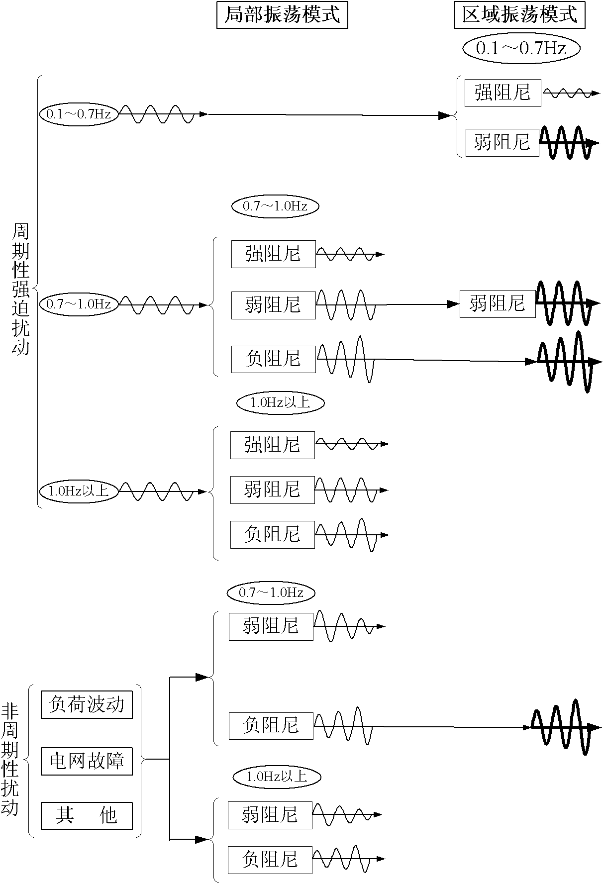
[0024] The discrimination method provided by the present invention is as follows:

[0025] (1) Introduction to the Judgment Principle of Oscillation Time of Multiple Measurement Points

[0026] Use the oscillation waveform recognition technology based on power data to determine whether the measurement point has started to vibrate, and record the corresponding start-up time.

[0027] (1.1) Oscillation Confirmation Conditions

[0028] 1. The oscillation period T satisfies: Tmin≤T≤Tmax, where Tmin and Tmax are usually set in the range of [0.4, 10] seconds;

[0029] 2.P max -P min ≥P set

[0030] (1.2) Counting methods of equal amplitude, increasing amplitude and decreasing amplitude oscillation

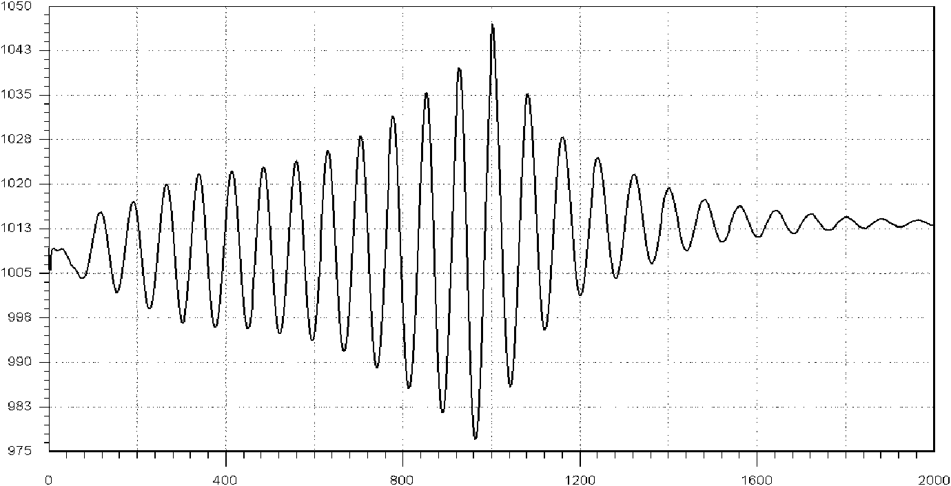
[0031] If it is judged to be an amplitude oscillation, the start-of-vibration discrimination counter will be +2;

[0032] It is judged as damping oscillation, if Then start the vibration discrimination counter -2, otherwise

[0033] Vibration discrimination counter - 1;

...


PUM


Abstract

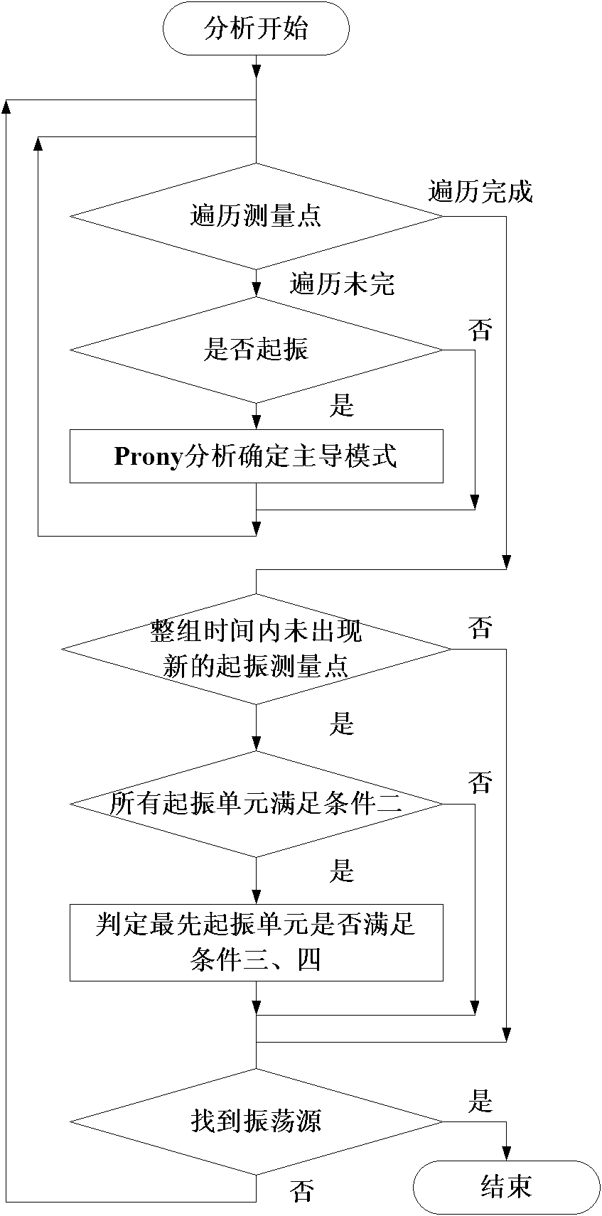
The invention discloses a method for positioning an oscillation disturbance source in a power system. The method comprises the following steps of: acquiring voltage, current, power physical quantity of a plurality of measuring points in a multi-voltage class power grid and meeting the following conditions: 1, whether each measuring point is subjected to low-frequency synchronous power oscillationis monitored in real time, and an oscillation amplitude, a main oscillation mode frequency, main oscillation mode damping, an initial phase of the main oscillation mode and oscillation initial time information are provided; 2, two frequencies in the main oscillation mode of the measuring points which are subjected to low-frequency oscillation accord with the condition that an absolute value of delta f is less than delta Fset; 3, the oscillation initial time of the measuring points which are subjected to low-frequency oscillation has a sequence relationship, and a clear characteristic that theoscillation starting time of measuring points in a low-voltage class power grid is earlier than the oscillation starting time of measuring points in a high-voltage class power grid; and 4, the average frequency fave of the main oscillation mode of each measuring point which is subjected to low-frequency oscillation accords with the condition that fave is more than fmin and less than fmax; and when the conditions are accorded, determining that the power system is subjected to low-frequency oscillation and a local power grid in an area with the earliest oscillation starting time is the oscillation disturbance source.

Description

technical field [0001] The invention relates to a method for locating an oscillation disturbance source in the low-frequency oscillation process of a power system, in particular to a new method for searching and locating an oscillation disturbance source by using wide-area multi-point oscillation information of a power grid. It is applied to the search and location of the low-frequency oscillation disturbance source of the power system in the safety and stability monitoring and control system, as well as related control measures for the oscillation source. Background technique [0002] With the implementation of my country's power construction policy of "power transmission from west to east, mutual aid between north and south, and regional networking", the situation of interconnection of major regions in the country has basically taken shape. Due to the relatively weak connection between the current large regions, low-frequency oscillations have occurred many times in the do...

Claims


Application Information

Patent Timeline
IPC IPC(8): H02J3/24G01R31/08
Inventor 李文云吴小辰陈松林孙光辉吴琛黄伟张丹柳勇军郭琦任祖怡毕兆东白杨俞秋阳
Owner NR ELECTRIC CO LTD
Why Eureka
Eureka Blog
Learn More