
Throttle body negative pressure testing device

A technology of a throttle body and a testing device, which is applied in the direction of measuring device, testing of mechanical parts, testing of machine/structural parts, etc., can solve problems such as the stability and improvement of the unfavorable throttle body, the inability to guarantee the product quality, the cumbersome operation process, etc. problem, to achieve the effect of simple structure, convenient operation and improved detection quality

Inactive Publication Date: 2011-07-13
SICHUAN HONGGUANG AUTO MACHINERY ELECTRONICS
View PDF3 Cites 1 Cited by
  • Summary
  • Abstract
  • Description
  • Claims
  • Application Information

AI Technical Summary

Problems solved by technology

[0003] However, most of the existing negative pressure test devices only have a nozzle with a fixed inner diameter, so a vacuum with a constant flow rate has to be used to test parts. Such negative pressure devices often cannot reliably and effectively simulate various working conditions of the engine. The product quality cannot be guaranteed, let alone meet the quality requirements of modern products. There are certain limitations in the related test extension of the throttle body, which is not conducive to the stability and improvement of the product quality of the throttle body. If you want to test different types of products, follow the In the prior art, different types of negative pressure testing devices need to be used, the operation process is very cumbersome, and multiple debugging is required, which is very easy to cause errors

Method used


Image

  • Throttle body negative pressure testing device
  • Throttle body negative pressure testing device
  • Throttle body negative pressure testing device

Examples


Embodiment Construction

[0013] The present invention will be further described below in conjunction with the accompanying drawings, but the scope of protection is not limited to the description.

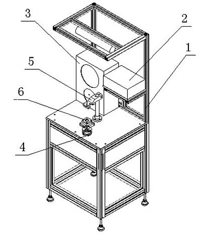
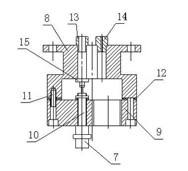
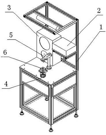
[0014] like figure 1 , throttle body negative pressure testing device, which includes aluminum alloy bench 1, stepper motor controller 2, negative pressure display 3, negative pressure switching chamber 4, clamping mechanism 5 and positioning platform 6, clamping mechanism 5 and The positioning platform 6 is fixed on the mounting plate including the aluminum alloy stand 1, the throttle body is fixed on the positioning platform 6 and clamped by the clamping mechanism 5, and the negative pressure switching chamber 4 is installed under the mounting plate, and the negative pressure switching chamber 4 is Switchable, the negative pressure switching chamber 4 is composed of an upper cover 8, a lower cover 9, a measuring hole, a threaded cylinder 10, a plug 15, an air inlet joint 7, and a connecting screw 11. At l...


PUM


Abstract

The invention discloses a throttle body negative pressure testing device, which comprises an aluminum alloy rack (1), a stepped motor controller (2), a negative pressure display (3), a negative pressure switching chamber (4), a clamping mechanism (5) and a positioning table (6), wherein the clamping mechanism (5) and the positioning table (6) are fixed on a mounting plate of the aluminum alloy rack (1); the negative pressure switching chamber (4) is arranged below the mounting plate, can be switched, and consists of an upper cover, a lower cover, measuring orifices, a threaded cylinder, end caps, an air inlet joint and a connecting bolt; at least two groups of measuring orifices of different type numbers are formed on the upper cover; and matched negative pressure nozzles and end caps are arranged on each measuring orifice. The throttle body negative pressure testing device can stably provide vacuum flows of various specifications to meet various negative pressure testing requirements of a throttle body and widen a testing range, is favorable for improving the detection quality of the throttle body product, and has the characteristics of simple structure, convenience of operation, high universality and the like.

Description

technical field [0001] The invention relates to a test device, in particular to a throttle body negative pressure test device. Background technique [0002] At present, negative pressure testing is involved in many industries, especially in the detection of engine-related parts in the automotive industry. After assembly, the actual working conditions of the engine will be simulated, and a certain flow of vacuum will be used to test the qualified parts. or not. [0003] However, most of the existing negative pressure test devices only have a nozzle with a fixed inner diameter, so a vacuum with a constant flow rate has to be used to test parts. Such negative pressure devices often cannot reliably and effectively simulate various working conditions of the engine. The product quality cannot be guaranteed, let alone meet the quality requirements of modern products. There are certain limitations in the related test extension of the throttle body, which is not conducive to the sta...

Claims


Application Information

Patent Timeline
IPC IPC(8): G01M13/00
Inventor 吴苏川肖传良杜昌学项劲涛
Owner SICHUAN HONGGUANG AUTO MACHINERY ELECTRONICS
Learn More