
Lock cylinder and antitheft mortise door lock adopting same

A technology of lock cylinder and lock cylinder shell, which is used in construction locks, cylinder pin locks, locks with turning keys, etc. Anti-technical opening ability, good bending strength, high sheet density

Active Publication Date: 2013-06-12
广州市运顺机电科技有限公司
View PDF5 Cites 0 Cited by
  • Summary
  • Abstract
  • Description
  • Claims
  • Application Information

AI Technical Summary

Problems solved by technology

The leaves of most leaf locks do not have a rotating shaft, and the leaves do not rotate around the rotating shaft. Such leaf locks are not smooth enough. When the size of the lock is small, such as the small size of "mortice lock", Page lock is not smooth enough
[0006] Chinese patent 2009201571442 proposes a leaf lock with a rotating shaft on the leaf, and the leaf rotates around the rotating shaft. Therefore, such a leaf lock should be relatively smooth, but because the design requires a lock cylinder, in most cases, The length of the lock is limited, and the lock core has a certain thickness interval, which reduces the number of plates placed in the lock of the same length, resulting in low security; the lock core must pass through the plates, so as to ensure that it can be used as a lock cylinder When idling, the relative position between each leaf and the lock cylinder remains unchanged, otherwise it cannot work normally; but the lock cylinder passes through the leaf, making the leaf become a semi-circular ring, which greatly weakens the bending strength of the leaf, when inserted or pulled out When the key is released, the thrust to the leaf will cause the semi-circular leaf to bend and not work normally; More than one millimeter, it is easy to be bent by the key, so it is difficult to apply to the mortise lock; in addition, the front end of the lock cylinder (key insertion end) of this patent is a boring structure, so the shaft must be inserted from the rear end, and the anti-drilling cover cannot be added. Can't do anti-drilling

Method used


Image

  • Lock cylinder and antitheft mortise door lock adopting same
  • Lock cylinder and antitheft mortise door lock adopting same
  • Lock cylinder and antitheft mortise door lock adopting same

Examples


Embodiment 1

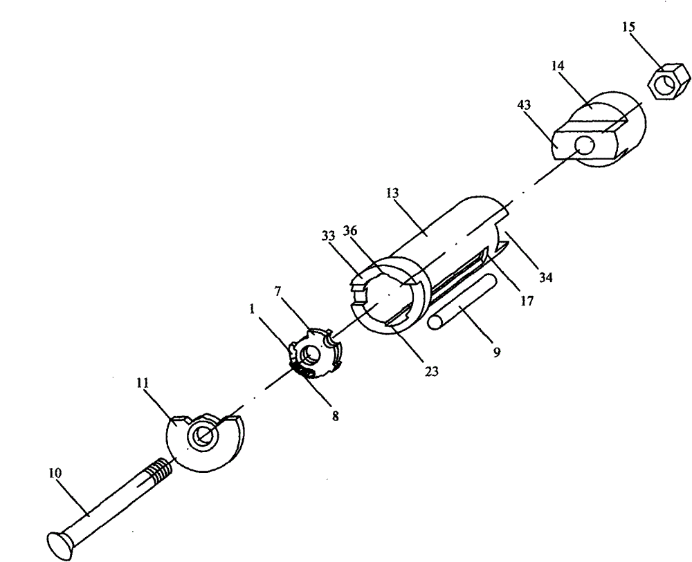
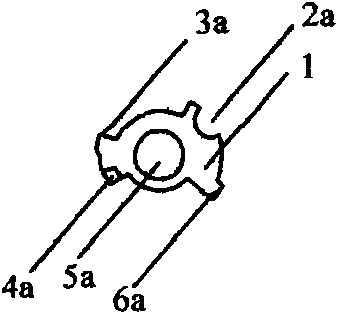
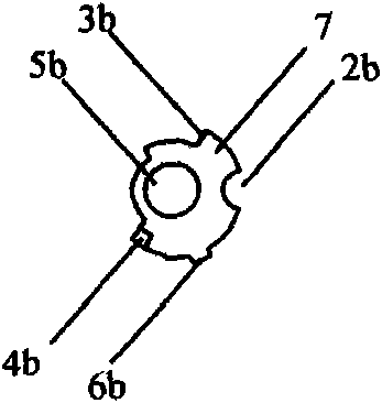
[0073] figure 1 It is an exploded view of the first embodiment of the lock cylinder of the present invention. The first embodiment of the lock cylinder 16 of the present invention includes a rotating shaft 10 , a front cover 11 , a left leaf 1 , a right leaf 7 , a spring 8 , a locking post 9 , a lock cylinder case 13 , a tail 14 and a nut 15 . The lock cylinder shell 13 is a hollow cylinder, with a first boss 33 at its front end and a groove 34 at its rear end. The front end of the tail part 14 has a second boss 43 . figure 1 Only a set of leaves consisting of left leaf 1, right leaf 7 and spring 8 is shown. In this embodiment, there are actually 5 sets of leaves. Each set of leaves is connected to the shaft 10. The left leaf 1 and the right leaf The pieces 7 can rotate around the rotating shaft 10 . Lock core outermost is the front cover 11 that is used for anti-drilling, and the central hole of front cover 11 is a circular hole, and the first boss 33 of front cover 11 and...

Embodiment 2

[0085] In the first embodiment of the lock cylinder 16 of the present invention, the position of the rotating shaft 10 is determined by the shaft holes on the front cover 11 and the tail 14, but the shaft holes on the front cover 11 and the tail 14 are difficult to ensure the axis of the rotating shaft 10 Aligned with the axis line of the lock cylinder shell 13, if the axis of the rotating shaft 10 deviates greatly from the axis line of the lock cylinder shell 13, the blades may rub against the inner wall of the lock cylinder shell 13, making the lock cylinder 16 does not work properly. In order to solve this problem, the front positioning sheet 12 can only be placed in front of the sheet group, and the rear positioning sheet 19 can only be placed behind the sheet group. Figure 14 , Figure 15 , Figure 16 with Figure 17 As shown, the second embodiment adopts the technical scheme of placing the front positioning piece 12 and the rear positioning piece 19 at the front and ...

Embodiment 3

[0089] In Embodiments 1 and 2 discussed above, the rotating shaft 10 encapsulates the leaf group in the lock cylinder case 13 through the front cover 11 , the tail portion 14 and the nut 15 . In this structure, the nut 15 takes up a lot of space, so that the number of sheets of the lock core 16 fails to reach the maximum. Figure 18 , Figure 19 with Figure 20 A third embodiment of the lock cylinder 16 of the present invention is shown. In this embodiment, there is a screw hole 56 on the tail part 14. Therefore, the screw hole 56 on the tail part 14 is directly used to screw on the thread at the tail end of the rotating shaft 10, and the nut 15 is eliminated to save the space it occupies. Figure 20 In the sectional view of the present embodiment, under the same lock cylinder length (the length of the mortise lock is 75 millimeters as the design length), a group of leaf sheets is added to reach 6 groups of 12 leaf sheets. In order to prevent the rotating shaft 10 from bein...


PUM


Abstract

The invention relates to a lock cylinder and an antitheft mortise door lock adopting the same, belonging to the field of antitheft products. In the lock cylinder, a rotating axle hole, a left locking cylindrical cavity, a left key surface, a left spring seat and a left limit fin are arranged on a left vane; a rotating axle hole, a right locking cylindrical cavity, a right key surface, a right spring seat and a right limit fin are arranged on a right vane; one end of a spring is buckled on the left spring seat, and the other end of the spring is buckled on the right spring seat; the left vane,the right vane and the spring form a vane group, and more than three vane groups are stringed into a rotating shaft from the rotating axle holes in a closely placed mode, and are encapsulated in a lock cylinder shell; a limit groove for placing the left limit fin and the right limit fin is formed on the wall of the lock cylinder shell; and a long groove for placing a locking cylinder is formed onthe lock cylinder shell. The lock cylinder has the advantages that: the lock cylinder has high vane density under a fixed length, stable performance, and strong prizing prevention, drilling prevention and technical opening resistance; and the antitheft mortise door lock has high safety, stable performance and the function of strong prizing prevention, drilling prevention and technical opening resistance.

Description

technical field [0001] The invention relates to a lock cylinder and a door lock adopting the lock cylinder, in particular to a lock cylinder with high leaf density and strong anti-prying, anti-drilling and anti-technical opening capabilities and an anti-theft plug adopting the lock cylinder core lock. Background technique [0002] The most widely used mortise lock is the Kaba lock. The Kabbah lock generally includes a lock body, a lock cylinder, a pin and a spring, a clutch and a puller. The pins of the Kabbah lock are cylindrical, and there are corresponding pin holes on the lock body and the lock cylinder. Each pin hole has two cylindrical pins and a spring. The pins are inserted between the lock body and the lock cylinder by the pressure of the spring. Pin pins are divided into spring pin pins and key pin pins. The key pin pins are always in the lock cylinder. One end of the spring pin pins is in contact with the key pin pins, and the other end is connected with the spr...

Claims


Application Information

Patent Timeline
Patent Type & Authority Patents(China)
IPC IPC(8): E05B15/00E05B29/06E05B15/14E05B17/00
Inventor 李巩令
Owner 广州市运顺机电科技有限公司
Learn More