Head air-suction mechanism for inserting machine

A technology of air suction mechanism and plug-in machine, applied in the direction of electrical components, electrical components, etc., can solve the problems of high difficulty in control, increase in scrap rate, and detachment of electronic components, and achieve the effects of reducing manufacturing costs, absorbing stably, and reducing damage

Inactive Publication Date: 2011-07-06
DONGGUAN SCIENCGO MACHINERY MFG
View PDF4 Cites 8 Cited by
  • Summary
  • Abstract
  • Description
  • Claims
  • Application Information

AI Technical Summary

Problems solved by technology

[0002] With the rapid development of the electronics industry, the application of electronic processing equipment is becoming more and more extensive, and the mechanical claw is a very commonly used device in electronic processing equipment. The mechanical claw is mainly used to pick up electronic components, and transport and install them on the circuit board. , but the existing manipulator claws are relatively expensive due to their complex structure and high control difficulty
[0003] In addition, it is relatively difficult to control the gripping force of the manipulator claws. When gripping electronic components, if the gripping force is too large, it is easy to damage the electronic components. This phenomenon is especially true for high-precision and easily deformable electronic components. Obviously, this will lead to a large increase in the scrap rate; if the clamping force is too small, it will easily cause the clamping to be not stable enough, and the electronic components will be detached from the mechanical claws, which will affect the normal production of the plug-in machine

Method used


Image

  • Head air-suction mechanism for inserting machine
  • Head air-suction mechanism for inserting machine
  • Head air-suction mechanism for inserting machine

Examples


Embodiment Construction

[0016] In order to facilitate the understanding of those skilled in the art, the present invention will be further described below in conjunction with the embodiments and accompanying drawings, and the contents mentioned in the embodiments are not intended to limit the present invention.

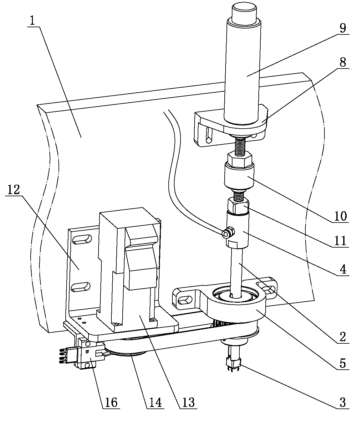
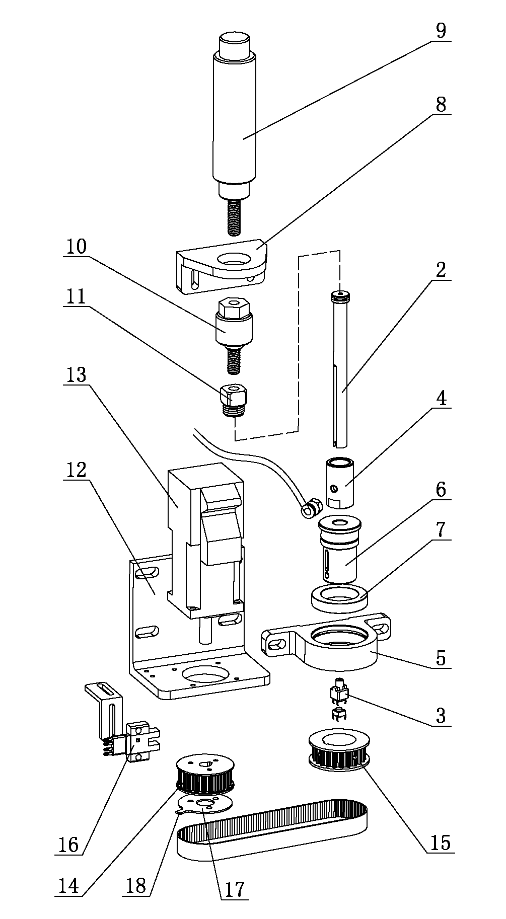
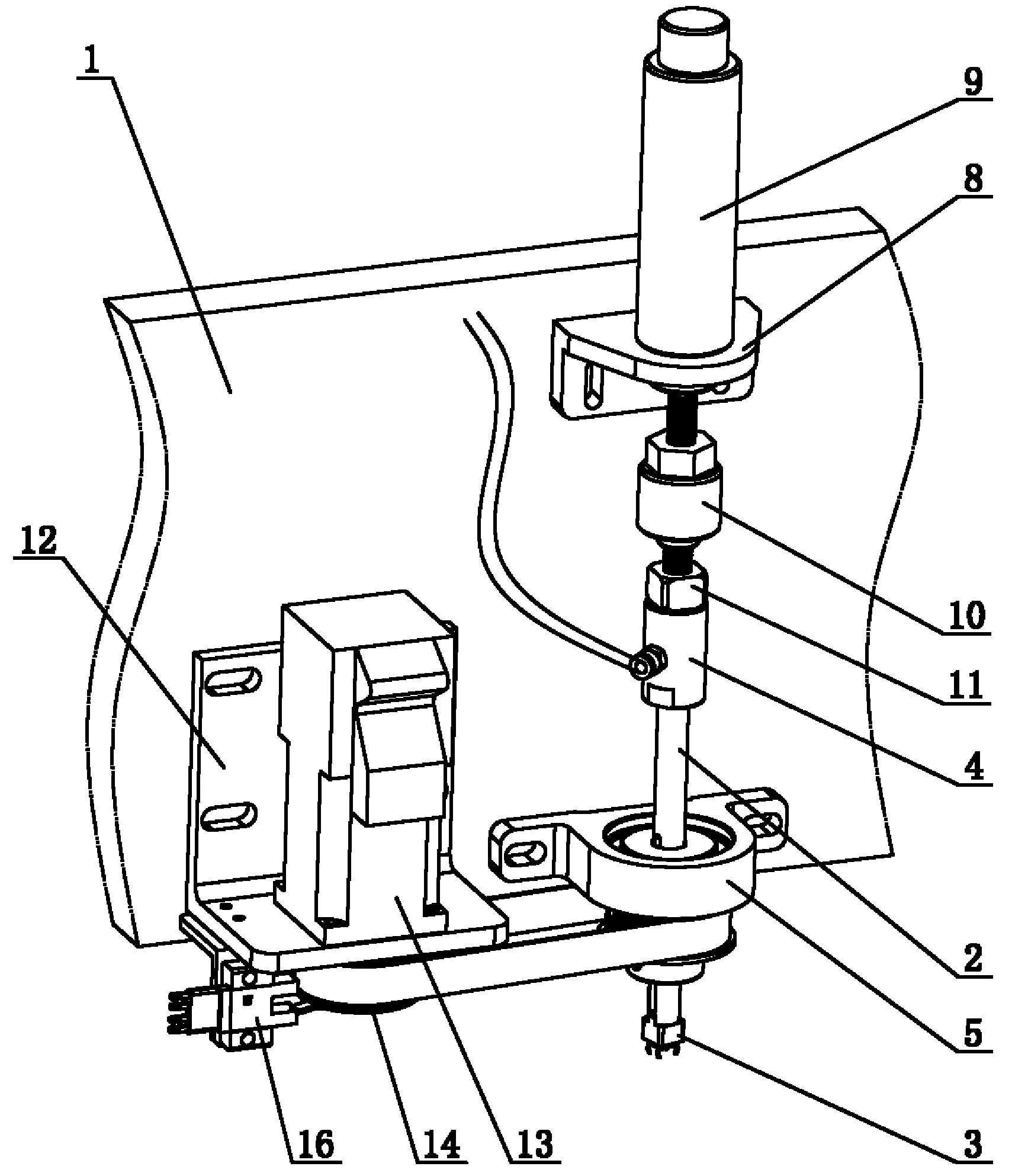
[0017] Such as figure 1 and figure 2 As shown, a head air suction mechanism for a plug-in machine includes a frame 1, a lifting mechanism arranged on the frame 1, and a corner mechanism arranged on the frame 1. The head air suction mechanism for a plug-in machine also includes a The suction rod 2 moving up and down and the suction nozzle 3 arranged at the lower end of the suction rod 2, the upper end of the suction rod 2 is connected with the lifting mechanism; the middle part of the suction rod 2 is provided with an air flow channel, and the suction rod 2 is equipped with It is convenient to connect the connecting sleeve 4 of the trachea joint; the corner mechanism includes a bearing seat...


PUM


Abstract

The invention belongs to the technical field of electronic component inserting machines and particularly relates to a head air-suction mechanism used for an inserting machine. The head air-suction mechanism used for the inserting machine comprises a machine frame, a lifting mechanism arranged on the machine frame and a corner mechanism arranged on the machine frame; the head air-suction mechanismused for the inserting machine further comprises a suction rod capable of moving up and down and a suction nozzle arranged at the lower end of the suction rod, wherein the upper end of the suction rod is connected with the lifting mechanism; an airflow passage is arranged in the middle of the suction rod, and a connecting sleeve conveniently connected with an air pipe connector is installed on the suction rod; and the corner mechanism comprises a bearing seat arranged on the machine frame, a corner sleeve installed on the bearing seat and a driving mechanism for driving the corner sleeve to rotate, wherein the suction rod is movably sleeved in the corner sleeve. The head air-suction mechanism used for the inserting machine has the advantages of simple structure, stableness in suction, greatly reduced manufacturing cost of equipment, reduced damage of electronic components and high practicability.

Description

technical field [0001] The invention relates to the technical field of electronic component insertion machines, in particular to a head air suction mechanism for an insertion machine. Background technique [0002] With the rapid development of the electronics industry, the application of electronic processing equipment is becoming more and more extensive, and the mechanical claw is a very commonly used device in electronic processing equipment. The mechanical claw is mainly used to pick up electronic components, and transport and install them on the circuit board. , but the existing manipulator claws have relatively high cost of processing equipment due to their complex structure and high difficulty in control. [0003] In addition, it is relatively difficult to control the gripping force of the manipulator claws. When gripping electronic components, if the gripping force is too large, it is easy to damage the electronic components. This phenomenon is especially true for hig...

Claims


Application Information

Patent Timeline
Patent Type & Authority Applications(China)
IPC IPC(8): H05K13/04
Inventor 钟显辉苏凯波黎旺肖华曾翔清陈卓标
Owner DONGGUAN SCIENCGO MACHINERY MFG
Why Eureka
Try Eureka