Electronic mutual inductor synchronization method based on PPS

An electronic transformer and second pulse technology, which is applied in the field of electronic transformer synchronization based on second pulse, to filter out interference pulses and solve the effect of cumulative deviation

Inactive Publication Date: 2011-07-06
XJ ELECTRIC +2
View PDF2 Cites 21 Cited by
  • Summary
  • Abstract
  • Description
  • Claims
  • Application Information

AI Technical Summary

Problems solved by technology

[0006] The purpose of the present invention is to provide a method for synchronizing electronic transformers based on second pulses to solve the problem of filtering out the burrs caused by plugging and unplugging optical fibers or interference and eliminating the cumulative deviation of the crystal oscillator due to the influence of the ambient temperature

Method used


Image

  • Electronic mutual inductor synchronization method based on PPS
  • Electronic mutual inductor synchronization method based on PPS
  • Electronic mutual inductor synchronization method based on PPS

Examples


Embodiment Construction

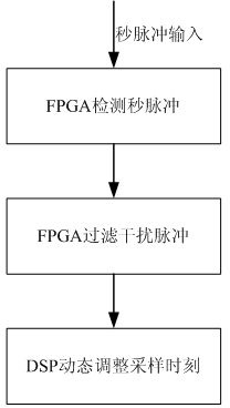
[0025] The method of the present invention is mainly applied to the merging unit, the merging unit is designed with an FPGA+DSP scheme, the FPGA is used for timing control, and the DSP is used for processing digital signals. Such as figure 1 Shown is a flowchart of an embodiment of the present invention. The merging unit receives the second pulse PPS output by the master clock of the synchronization system in the smart substation, and the merging unit uses the field gate programming gate array FPGA inside to detect the PPS signal, and filter out the interference pulse according to the crystal oscillator count The DSP in the merging unit determines the interpolation time, that is, the re-sampling time, according to the PPS punctual time and the sampling rate of the merging unit. At the same time, the DSP dynamically compensates the crystal oscillator deviation by dynamically adjusting the re-sampling time.

[0026] The merging unit receives the PPS (pulses per second, abbreviated a...


PUM


Abstract

The invention relates to an electronic mutual inductor synchronization method based on PPS. A merging unit receives a pulse per second (PPS) output by a master clock of a synchronization system in an intelligent transformer substation; the merging unit utilizes a field programmable gate array (FPGA) inside to detect a PPS signal, and filters interference pulses according to crystal count; and a digital signal processor (DSP) in the merging unit determines an interpolation moment, namely a resampling moment according to a PPS on-time moment and a sampling rate of the merging unit, and simultaneously the DSP compensates the crystal deviation dynamically through dynamic adjustment of the resampling moment. The electronic mutual inductor synchronization method not only can recognize correct PPS, but also can filter interference pulses without influencing receiving of the correct PPS, and simultaneously can track the synchronous state of a GPS clock quickly when a master clock is switched from an asynchronous state to a synchronous state; when the factors such as the environment temperature and the like are changed, the output data synchronization error is not larger than plus / minus 1 mus through dynamic adjustment of the resampling moment by the DSP, thus not only solving the problem of cumulative deviation, but also meeting the requirement of automation equipments of the intelligent transformer substation for protection, measurement and control, metering and the like.

Description

Technical field [0001] The invention relates to a sampling synchronization method for an electronic transformer merging unit in an intelligent substation, in particular to a second pulse-based electronic transformer synchronization method. Background technique [0002] As the transmission capacity of the power system increases and the operating voltage level is getting higher and higher, the traditional electromagnetic current and voltage transformers have exposed a series of shortcomings such as high insulation requirements, magnetic saturation, ferromagnetic resonance, small dynamic range and narrow frequency bands. As a result, electronic current and voltage transformers, which are designed to solve the problems of ultra-high voltage insulation and magnetic saturation, have emerged. In recent years, research on electronic current and voltage transformers has developed rapidly, and current transformers based on optical and Rogowski air-core coils have entered the practical stag...

Claims


Application Information

Patent Timeline
IPC IPC(8): H02B1/24H03K5/1252
Inventor 张克元李富生李瑞生周水斌赵应兵马朝阳
Owner XJ ELECTRIC
Why Eureka
Try Eureka