Single-unit beam-splitting short-baseline parallel-optical-axis binocular stereo imaging method and device thereof

A technology of binocular stereo, imaging method, applied in stereo photography, optics, instruments, etc., can solve the problems of reducing the reconstruction robustness of the single-machine beam splitting structure, unable to meet the translation assumption of the matching map pair, etc., and achieve easy imaging. Poorly optimized, fully utilized, and captured with precise synchronization

Inactive Publication Date: 2011-07-06
杭州大清智能技术开发有限公司
View PDF2 Cites 3 Cited by
  • Summary
  • Abstract
  • Description
  • Claims
  • Application Information

AI Technical Summary

Problems solved by technology

[0005] The purpose of the present invention is to overcome the difficulties that the existing binocular system uses a dual-machine structure to reduce the reconstruction robustness or the single-machine beam splitting structure cannot satisfy the translation assumption of the matching graph. The present invention provides a single-machine binocular short-baseline parallel Optical axis stereoscopic imaging method and its device, the device has the characteristics of simple installation, equal beam splitting optical path, same structure, full symmetry of optical system, easy aberration optimization, parallel optical axes, short baseline, conforming to translational assumptions, etc.

Method used


Image

  • Single-unit beam-splitting short-baseline parallel-optical-axis binocular stereo imaging method and device thereof
  • Single-unit beam-splitting short-baseline parallel-optical-axis binocular stereo imaging method and device thereof
  • Single-unit beam-splitting short-baseline parallel-optical-axis binocular stereo imaging method and device thereof

Examples


Embodiment Construction

[0014] The patent of the present invention will be further described below through the embodiments in conjunction with the accompanying drawings.

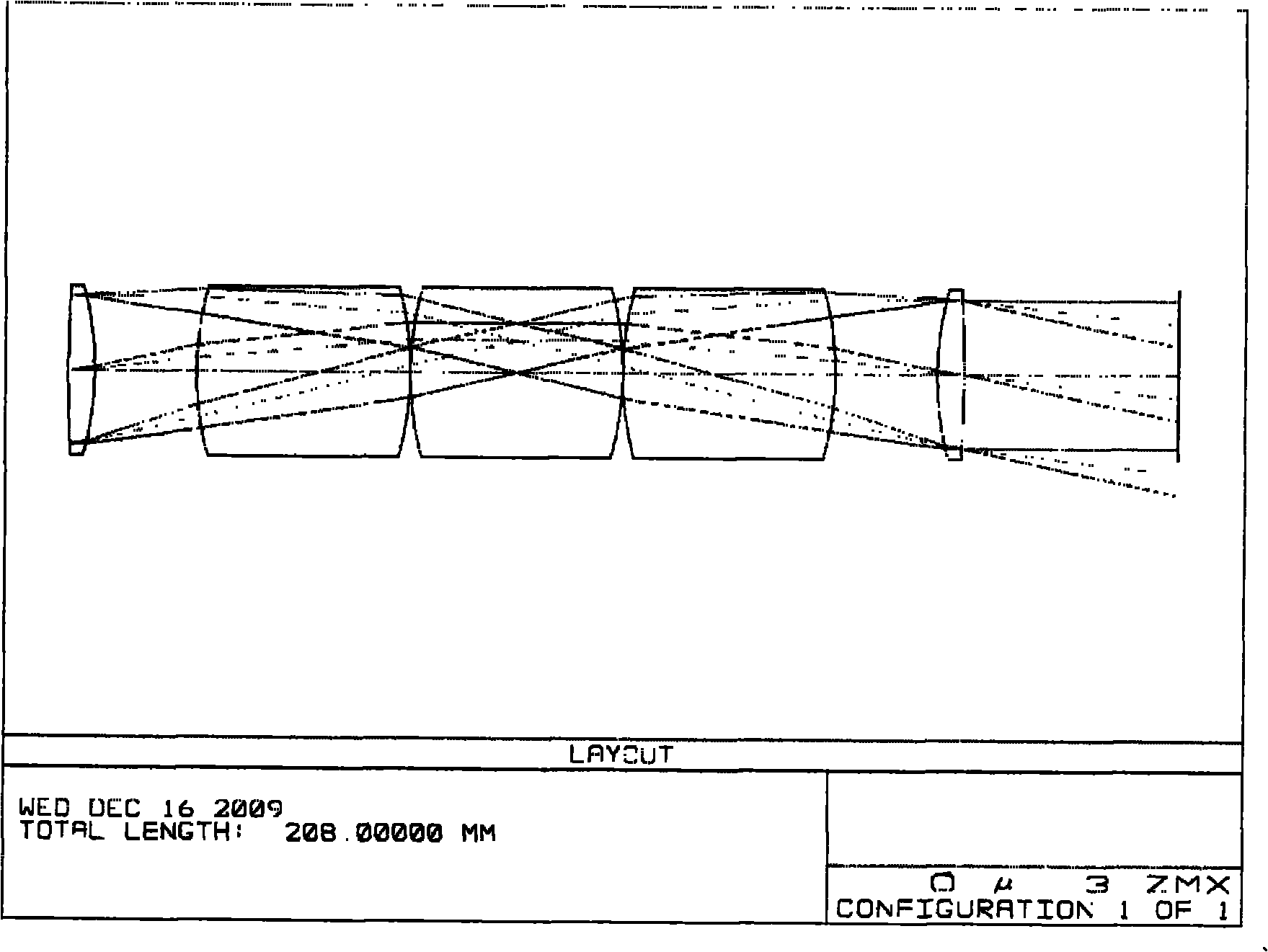
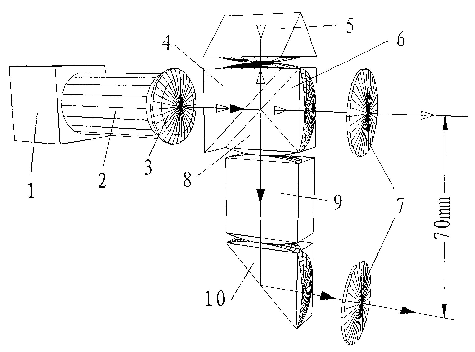
[0015] Such as figure 1 As shown, in this example, an additional beam splitting accessory is added to the front end of the industrial camera (1) to achieve binocular stereoscopic imaging. Part of the light emitted from the subject passes through the objective lens (7) of the beam-splitting attachment below, and successively passes through the transfer prism (10), the cube prism (9), and the transfer prism (8) of the plano-convex lens glued on the incident surface, and the beam is split. The accessory eyepiece (3) is convergent for the camera objective lens (2), and forms a clear image on the right half of the CCD target surface of the industrial camera (1). Another part of light emitted from the same object passes through the objective lens (7) of the upper beam-splitting attachment, successively passes through three conversion pr...


PUM


Abstract

The invention discloses a single-unit beam-splitting short-baseline parallel-optical-axis binocular stereo imaging method and a device thereof. The method and the device are realized by additionally arranging a beam-splitting fitting in front of an objective. Part of light beams emitted by a photographed body passes by a subjacent biconvex lens and sequentially passes by an inverting prism, a cubic prism, an inverting prism and the biconvex lens with the light inlet surface and light outlet surface glued with flat convex lenses, and is gathered at the objective, thus forming clear images on the right half part of the CCD target surface of the camera. The other part of light beam emitted by the same object passes by the biconvex lens above and sequentially passes by the inverting prisms and the biconvex lens with three light inlet surfaces and light outlet surfaces glued with flat convex lenses, and is gathered at the objective, thus forming clear images at the left half part of the CCD target surface. The method and the device have the benefits that the image pairs can be collected precisely and synchronously compared with a dual-unit system; the binocular optical axis is paralleland the baseline is short; the beam-splitting light has the same light stroke and consistent image depth; and the upper optical structure and the lower optical structure of the beam-splitting fittingare consistent and have symmetry; and the pixel is easy to optimize.

Description

technical field [0001] The invention relates to a stereoscopic imaging technology, in particular to a single-machine binocular short-baseline parallel optical axis stereoscopic imaging method and a device thereof. Background technique [0002] In binocular stereo vision, in order to accurately obtain dense 3D reconstructed point cloud information, it is usually first necessary to build a parallel optical axis system with a short baseline for image acquisition, so as to satisfy the assumption that the small neighborhoods around the conjugate points can be regarded as mutual translation . Then, the precise registration of conjugate points is realized through the theory of image translation invariance in frequency domain. A Chinese patent discloses a fast three-dimensional face recognition method based on binocular passive stereo vision (publication number: CN101398886), which follows the above assumptions. Stereoscopic photography of non-stationary objects is generally achie...

Claims


Application Information

Patent Timeline
Patent Type & Authority Applications(China)
IPC IPC(8): G03B35/00
Inventor 不公告发明人
Owner 杭州大清智能技术开发有限公司
Why Eureka
Try Eureka