
Fan system and brake circuit thereof

A fan system and circuit technology, applied in the direction of motor generator/starter, cooling/ventilation/heating transformation, starter of a single DC motor, etc., can solve the problems of increasing circuit connection complexity and control complexity, etc., to achieve The effect of reducing circuit cost and reducing the complexity of circuit connection

Inactive Publication Date: 2011-07-06
SUNONWEALTH ELECTRIC MACHINE IND
View PDF5 Cites 9 Cited by
  • Summary
  • Abstract
  • Description
  • Claims
  • Application Information

AI Technical Summary

Problems solved by technology

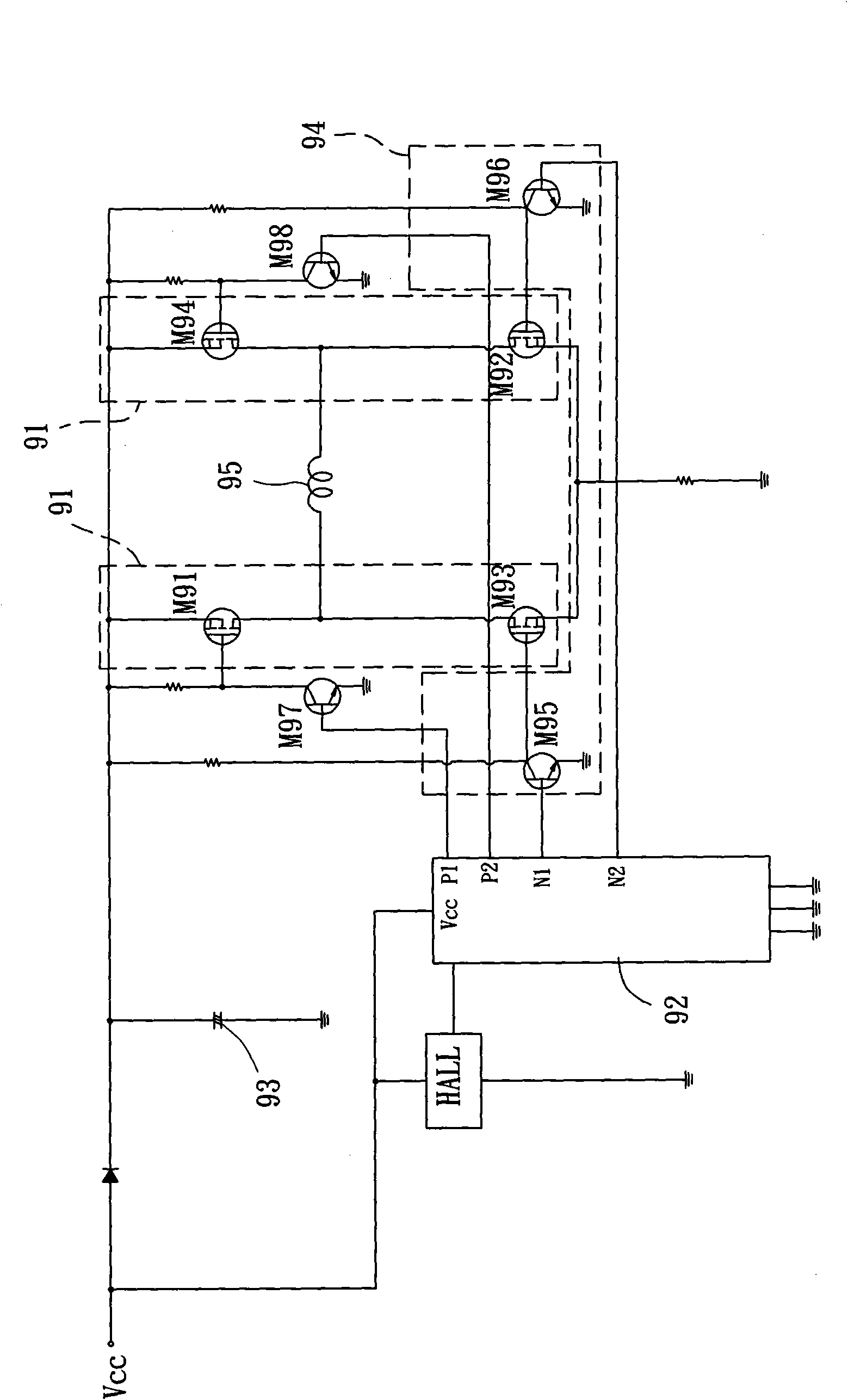
[0007] However, generally speaking, the above-mentioned prior art has the following disadvantages, for example: the fan system needs to be controlled by the instant stop unit 94 to perform an instant stop operation when the power is cut off
Relatively, the fan system will inevitably increase the complexity of circuit connection, increase the complexity of control and increase the cost of circuit setting due to the setting of the instant stop unit 94

Method used


Image

  • Fan system and brake circuit thereof
  • Fan system and brake circuit thereof
  • Fan system and brake circuit thereof

Examples


Embodiment Construction

[0044] In order to make the above-mentioned and other objects, features and advantages of the present invention more obvious and understandable, the preferred embodiments of the present invention are specifically cited below, together with the accompanying drawings, and are described in detail as follows:

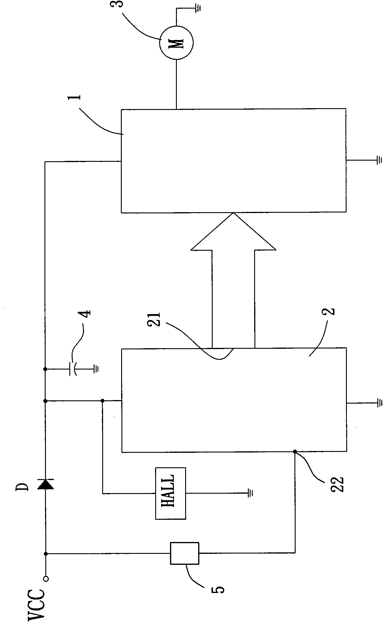
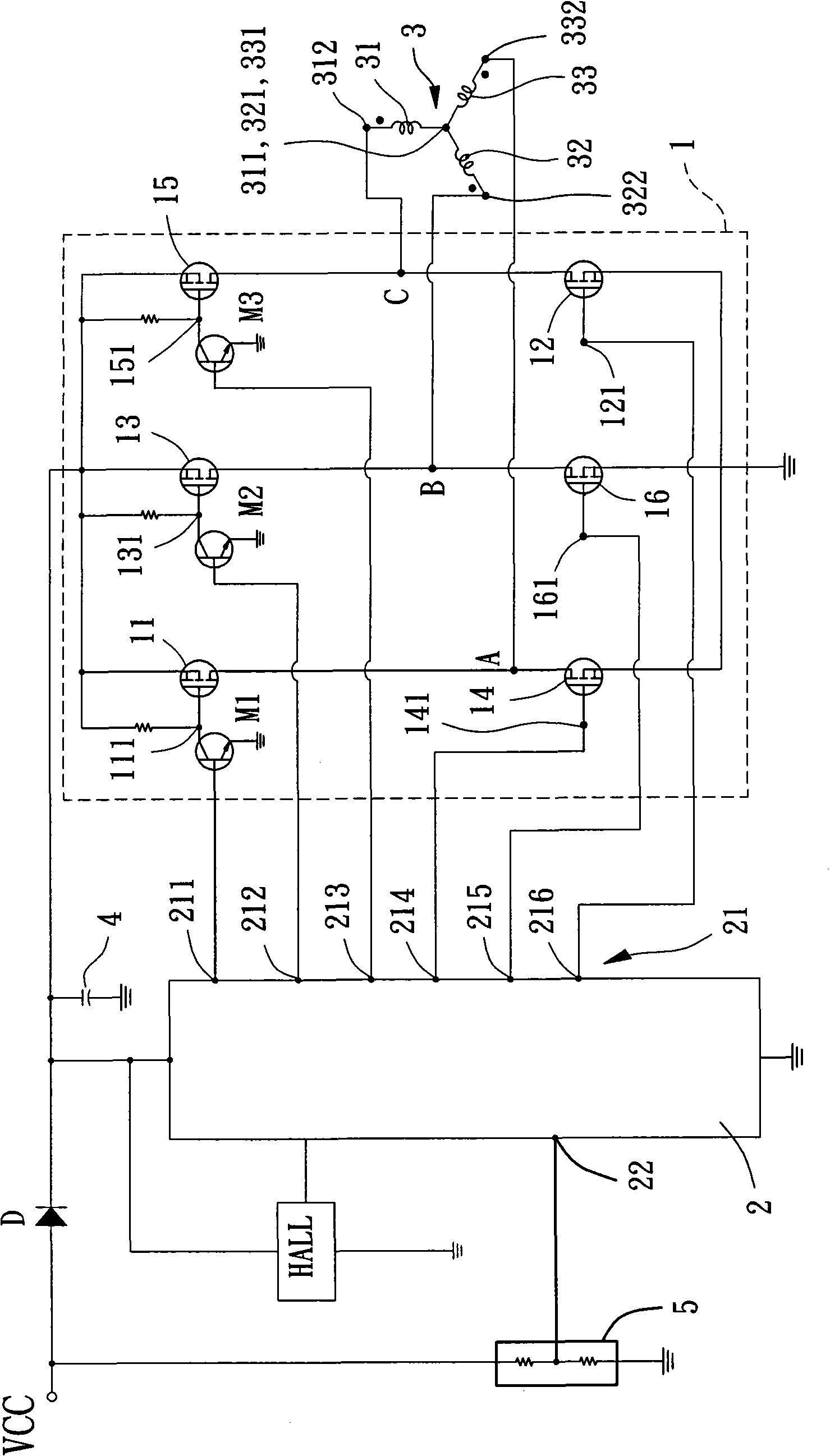
[0045] Please refer to figure 2As shown, it discloses the fan system and its brake circuit of the preferred embodiment of the present invention, wherein the fan system includes a motor drive circuit 1 , a control unit 2 , a motor 3 and an energy storage unit 4 . One of the input voltages VCC is electrically connected to the motor drive circuit 1, the control unit 2 and the energy storage unit 4 through a diode D, in other words, the motor drive circuit 1, the control unit 2 and the energy storage unit 4 are electrically connected to the diode D A cathode of the diode D, so that the input voltage VCC can provide the power required by the above-mentioned components through t...


PUM


Abstract

The invention discloses a fan system and a brake circuit thereof, which comprises a motor, a motor drive circuit, and a control unit. The motor drive circuit is electrically connected with the motor; the control unit is electrically connected with the motor drive circuit; when an input voltage is supplied to electrify the fan system, the control unit generates a forward rotation control signal to control the motor to rotate along a preset direction; when power supply of the input voltage to the fan system is interrupted, the control unit generates a reverse rotation control signal to control the motor to rotate along a direction opposite to the preset direction so as to brake and stop the motor instantly.

Description

technical field [0001] The present invention relates to a fan system and its brake circuit, especially to a fan system and its brake circuit which uses a control unit to send a reverse rotation control signal to control the fan system to stop rotating. Background technique [0002] In recent years, the use of a digital microcontroller (Micro-Controller Unit, MCU) combined with a power electronic switch drive circuit to design electronic products has become a commonly used technology in the industry. However, when operating the electronic product, the digital microcontroller and the power electronic switch will cause the electronic product to generate a lot of heat due to high frequency operation; therefore, the heat dissipation requirement of the electronic product will become a very important design issue. [0003] At present, the more common heat dissipation method uses the operation of the fan system to drive the wind and heat dissipation of the electronic product. Howeve...

Claims


Application Information

Patent Timeline
Patent Type & Authority Applications(China)
IPC IPC(8): F04D27/00F04D25/08H02P1/22H05K7/20
Inventor 洪银树侯冠印郑宗根章守坚伍家进
Owner SUNONWEALTH ELECTRIC MACHINE IND
Learn More