
Leg adjusting device and mobile crane

A mobile crane and adjusting device technology, applied in cranes and other directions, can solve the problems of weak bearing capacity, low thread tooth strength, large difference in thermal expansion coefficient, etc., and achieve strong bearing capacity, long service life and stable performance. Effect

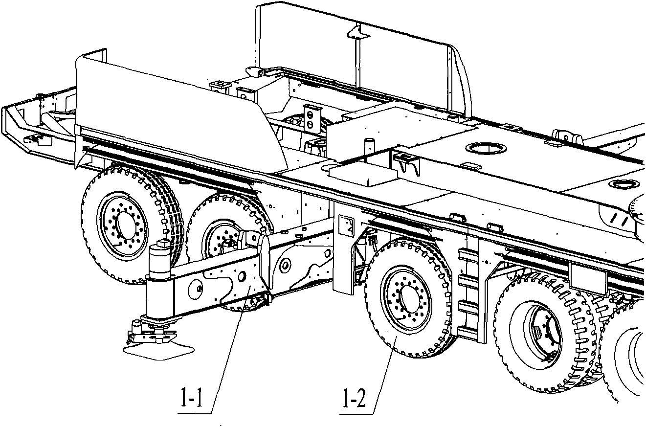
Inactive Publication Date: 2011-07-06
XUZHOU HEAVY MASCH CO LTD
View PDF0 Cites 0 Cited by
  • Summary
  • Abstract
  • Description
  • Claims
  • Application Information

AI Technical Summary

Problems solved by technology

[0012] First of all, because the material of nylon bolts is engineering plastics, its strength and rigidity are limited, and the thread teeth formed by processing are soft and low in strength, and their bearing capacity is weak. Gradually moving outward, the pressure on the nylon bolts also gradually increases, and tripping often occurs
[0013] Secondly, because the material of the upper cover plate of the second movable arm is structural steel, which is different from the material of nylon bolts, the thermal expansion coefficients of the two materials are quite different, which leads to the thread fit is greatly affected by the environment, and the performance is not stable enough
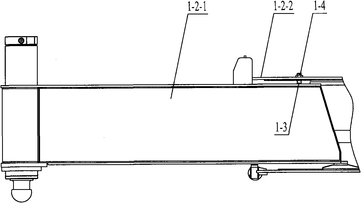
[0014] Furthermore, since the nylon bolts are arranged on the upper cover of the second movable leg, it is necessary to reserve a certain length of adjustment, which will occupy a certain space in the fixed leg during expansion and contraction. In the case of limited structural space, The cross-sectional size of the first movable outrigger and the second movable outrigger is small, resulting in a reduction in the space utilization of the outrigger cross section

Method used


Image

  • Leg adjusting device and mobile crane
  • Leg adjusting device and mobile crane
  • Leg adjusting device and mobile crane

Examples


Embodiment Construction

[0056] The core of the present invention is to provide an outrigger adjusting device, which is installed at the rear of the first movable outrigger, the whole device can withstand relatively large pressure, not only can be adjusted conveniently, but also does not occupy the space of the fixed outrigger. The internal space maximizes the cross-sectional size of the movable outrigger. Another core of the present invention is to provide a mobile crane including the above outrigger adjusting device.

[0057] In order to enable those skilled in the art to better understand the solution of the present invention, the present invention will be further described in detail below in conjunction with the accompanying drawings and specific embodiments.

[0058] Please refer to Figure 4 , Figure 5 , Figure 4 An exploded schematic diagram of the outrigger adjustment device provided by the present invention installed at the rear of the first section of outriggers; Figure 5 for Figure...


PUM


Abstract

The invention discloses a leg adjusting device which is used for a mobile crane. The leg adjusting device comprises a fixed bearing, a slide block, an adjusting block, a roll ball and an adjusting screw, wherein, the fixed bearing is arranged at the rear part of a first movable leg of the mobile crane, the top part of the fixed bearing is equipped with a slide hole with an upward opening and a base, and the side face of the fixed bearing is equipped with a threaded hole which is vertically communicated with the slide hole with the base at the position close to the bottom part; the slide block is arranged in the slide hole of the fixed bearing; the adjusting block is arranged below the slide block, and the bottom of the adjusting block is equipped with a wedge chute; the roll ball is positioned in the wedge chute of the adjusting block; and the adjusting screw is screwed into the threaded hole on the side face of the fixed bearing, and the end part of the adjusting screw props against the roll ball. The leg adjusting device can bear greater pressure and adjust the legs conveniently without occupying space in fixed legs so as to maximize section size of the movable legs. The invention further discloses the mobile crane comprising the leg adjusting device.

Description

technical field [0001] The invention relates to the technical field of engineering machinery, in particular to an outrigger adjusting device for a mobile crane. The invention also relates to a mobile crane comprising an outrigger adjustment device as described above. Background technique [0002] With the rapid development of my country's economic construction, the market demand for mobile cranes, especially medium and large tonnage mobile cranes, is increasing day by day. [0003] Please refer to figure 1 , figure 1 It is a schematic diagram of the chassis structure of the mobile crane. [0004] The mobile crane is a crane with automatic walking function. In addition to the wheels 1-1, the chassis is generally equipped with telescopic outriggers 1-2. The telescopic outriggers 1-2 are mainly composed of fixed outriggers. It is composed of movable outriggers and movable outriggers, among which the fixed outriggers are a part welded into a box-shaped structure made of stee...

Claims


Application Information

Patent Timeline
Patent Type & Authority Applications(China)
IPC IPC(8): B66C23/78
Inventor 朱磊周陆军王新强
Owner XUZHOU HEAVY MASCH CO LTD
Learn More