Anti-rotation ejection mechanism for automotive mold

A technology of jacking mechanism and automobile mould, which is applied in the field of anti-rotation jacking mechanism, which can solve the problems of high cost, large demand space, and unstable lifting of parts, and achieve the effect of simple structure and low cost

Active Publication Date: 2013-03-20
TIANJIN MOTOR DIES
View PDF7 Cites 1 Cited by
  • Summary
  • Abstract
  • Description
  • Claims
  • Application Information

AI Technical Summary

Problems solved by technology

[0002] At present, there are usually two types of jacking devices used in automobile molds. One is the H-type lifter. The jacking device with this structure has defects such as large space requirements and high cost. The feature of the feeding device is that the ejector rod is directly installed on the joint of the cylinder, which has defects such as easy rotation of the ejector rod and unstable lifting of the workpiece.

Method used


Image

  • Anti-rotation ejection mechanism for automotive mold
  • Anti-rotation ejection mechanism for automotive mold

Examples


Embodiment

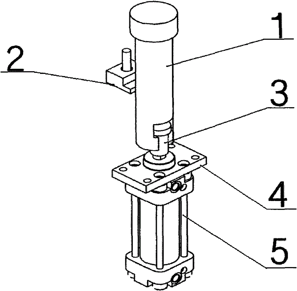
[0011] An anti-rotation jacking mechanism for automobile moulds, including a piston rod connecting rod 1, a pressure plate 2, a cylinder joint 3, a cylinder front flange 4 and a cylinder 5, and the piston rod connecting rod 1 is a T-shaped cylinder and is arranged on the mold In the lower mold body 6, the piston rod connecting rod 1 includes a T-shaped top at the upper end, a connecting rod in the middle and a groove at the lower end. The height is the same, and there is an anti-rotation plane on the connecting rod; the cylinder 5 is fixed on the lower mold body 6 of the mold through the cylinder front flange 4, the cylinder joint 3 is fixed with the cylinder 5 through threaded connection, and the cylinder joint 3 is inserted into the piston rod connecting rod 1 In the groove; the pressure plate 2 is fastened on the lower mold body 6 of the mold by screws, and its vertical surface is slidingly matched with the anti-rotation plane on the piston rod connecting rod 1.

[0012] Wh...


PUM


Abstract

The invention discloses an anti-rotation ejection mechanism for an automotive mold, which comprises a piston rod connecting rod, a pressure plate, a cylinder joint, a cylinder front flange and a cylinder, wherein the piston rod connecting rod is a T-shaped cylinder body and arranged in a lower mold body of the mold, the piston rod connecting rod comprises a T-shaped top at the upper end, a connecting rod in the middle part and a groove at the lower end, and the connecting rod is provided with an anti-rotation plane; the cylinder is fixed on the lower mold body of the mold by the cylinder front flange, the cylinder joint is fixed with the cylinder through threaded connection and sheathed in the groove of the piston rod connecting rod; and the pressure plate is fastened on the lower mold body of the mold by screws, and the vertical surface of the pressure plate is in sliding fit with the anti-rotation plane of the piston rod connecting rod. The anti-rotation ejection mechanism for the automotive mold has the advantages of simple and compact structure, and low manufacturing cost; as the main devices of the anti-rotation ejection mechanism are all arranged at the back of the lower mold, the mold becomes attractive and can conveniently and stably eject a manufacturing part, so that the manufacturing part can move along an ideal motion track so as to ensure that the manufacturing part can not influence the surface quality due to disordered rotation.

Description

technical field [0001] The invention relates to an automobile mold ejecting device, in particular to an anti-rotation ejecting mechanism for an automobile mould. Background technique [0002] At present, there are usually two types of jacking devices used in automobile molds. One is the H-type lifter. The jacking device with this structure has defects such as large space requirements and high cost. The feature of the feeding device is that the ejector rod is directly installed on the joint of the cylinder, which has defects such as easy rotation of the ejector rod and unstable lifting of the workpiece. Contents of the invention [0003] The purpose of the present invention is to overcome the above disadvantages, to provide a simple structure, compact, low cost, which can be conveniently used in the field of automotive mold jacking, to ensure that the parts do not rotate when they are lifted, and to protect the surface quality of the parts. The anti-rotation ejector mechan...

Claims


Application Information

Patent Timeline
Patent Type & Authority Patents(China)
IPC IPC(8): B29C33/44
Inventor 梁利成李君君常青
Owner TIANJIN MOTOR DIES
Why Eureka
Try Eureka