Eureka AIR delivers breakthrough ideas for toughest innovation challenges, trusted by R&D personnel around the world.

High-voltage battery charging system architecture of electric automobile

A high-voltage battery and electric vehicle technology, which is applied in the direction of electric vehicle charging technology, electric vehicles, battery circuit devices, etc., can solve the problems of complex winding process of transformers, increased circuit loss, long charging time, etc., and achieves low manufacturing cost and reduced loss , The effect of short charging time

Inactive Publication Date: 2011-06-29
DELTA ELECTRONICS INC
View PDF4 Cites 13 Cited by
  • Summary
  • Abstract
  • Description
  • Claims
  • Application Information

AI Technical Summary

Problems solved by technology

In the existing products, the charger adopts an isolated system architecture, and the transformer is a necessary component of the isolated DC-DC converter in the path of electric energy transmission, because the transformer will generate magnetic loss during the process of electric energy conversion (iron loss) and line loss (copper loss), which not only increases the loss of the circuit, but also the charging time of electric vehicles or hybrid vehicles will be relatively long
In addition, due to the isolation between the primary winding and the secondary winding of the transformer, it is necessary to add insulating tape or use three-layer insulated wire in the process of manufacturing the transformer, which makes the process of transformer winding more complicated and relatively costly. higher

Method used


Image

  • High-voltage battery charging system architecture of electric automobile
  • High-voltage battery charging system architecture of electric automobile
  • High-voltage battery charging system architecture of electric automobile

Examples


Embodiment Construction

[0036] Some typical embodiments embodying the features and advantages of the present invention will be described in detail in the description in the following paragraphs. It should be understood that the present invention is capable of various changes in different ways without departing from the scope of the present invention, and that the description and drawings therein are illustrative in nature rather than limiting the present invention.

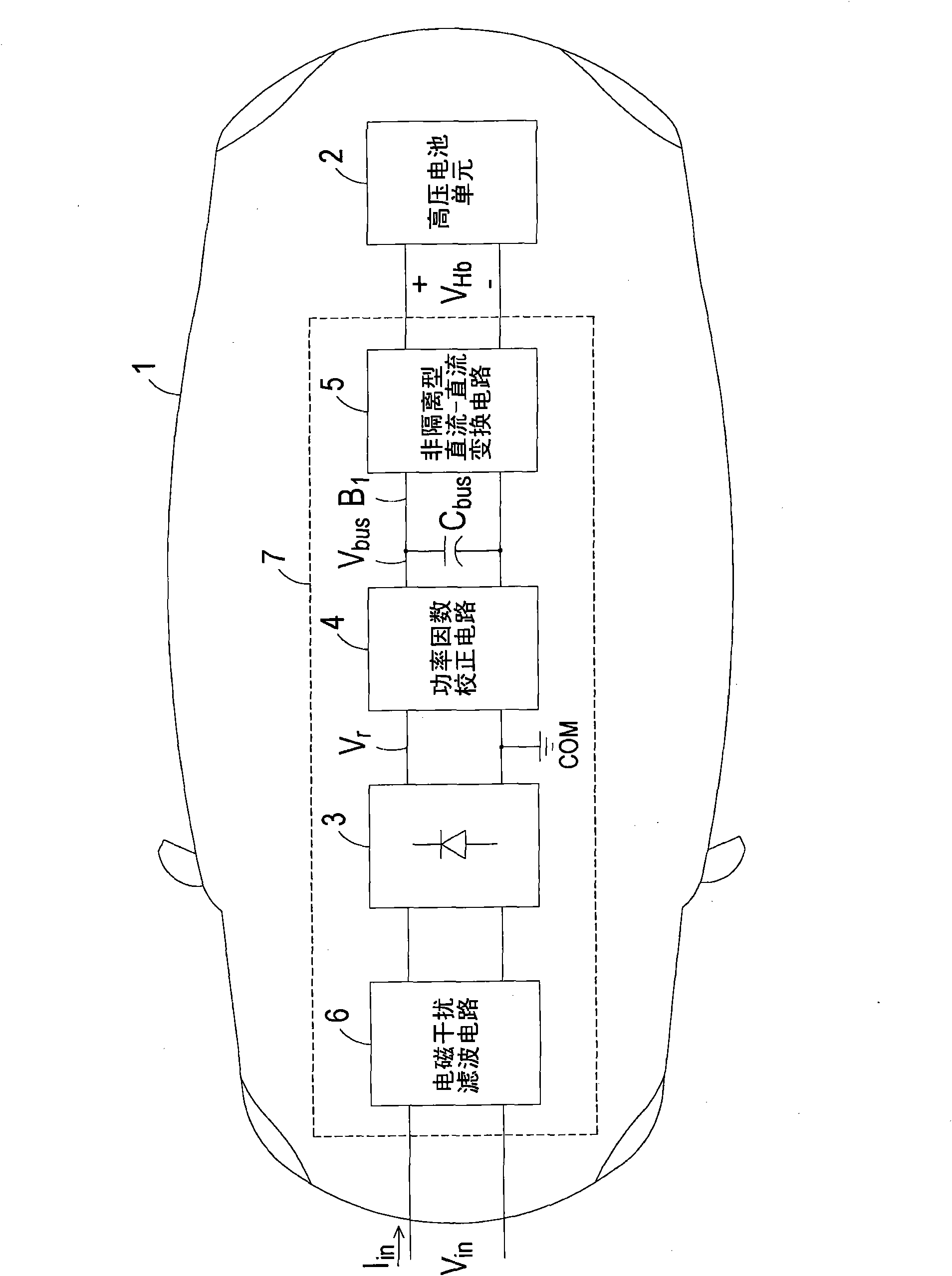
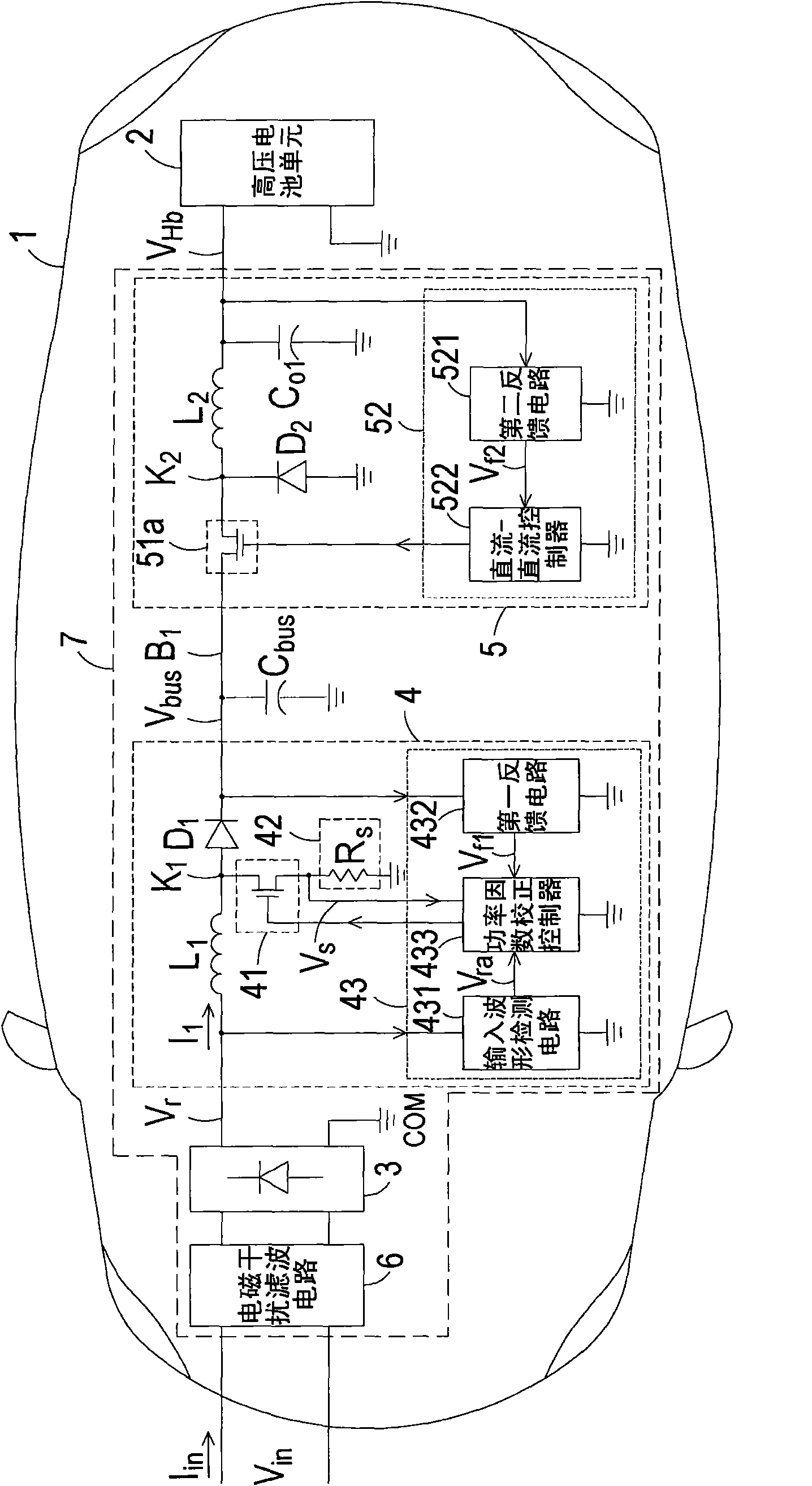
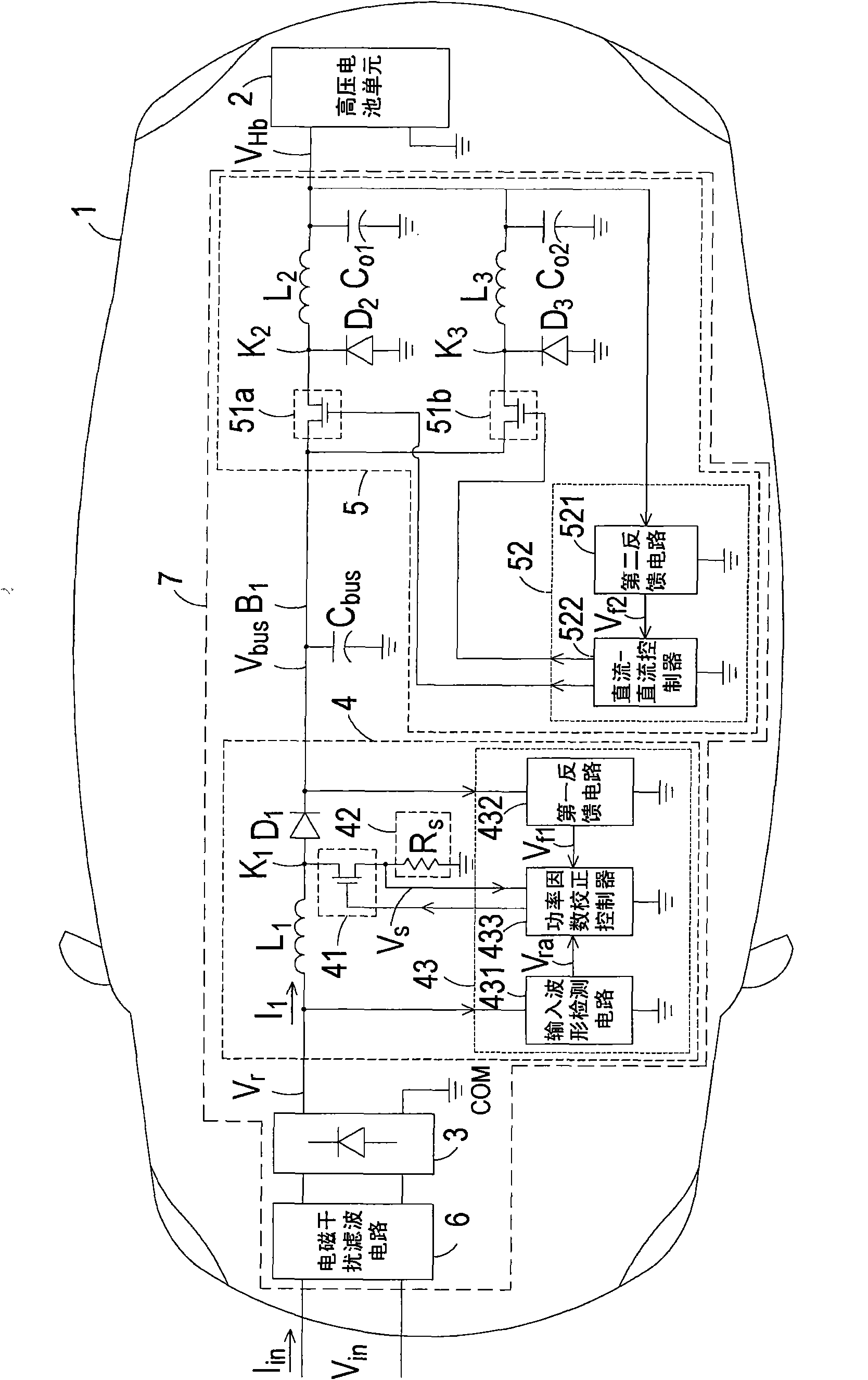
[0037] see figure 1 , which is a schematic diagram of the structure of the high-voltage battery charging system for electric vehicles according to a preferred embodiment of the present invention. Such as figure 1 As shown, the architecture of the high-voltage battery charging system of the electric vehicle is set in the body 1 of the electric vehicle to receive the AC input voltage V in (mains power) to charge the high-voltage battery unit 2, which includes: a rectifier circuit 3, a power factor correction circuit 4 (Power Factor Corre...


PUM


Abstract

The invention discloses a high-voltage battery charging system architecture of an electric automobile. The high-voltage battery charging system architecture is arranged in a car body and is used for receiving electric energy of alternating current input voltage so as to charge a high-voltage battery unit in the car body. The high-voltage battery charging system architecture comprises a rectification circuit, a power factor correcting circuit, and a non-isolated type DC-DC converting circuit, wherein the rectification circuit is connected with a common connection point and is used for rectifying the alternating current input voltage to generate rectified voltage; the power factor correcting circuit is connected with the rectification circuit and a bus, and is used for improving power factors and generating bus voltage; the non-isolated type DC-DC converting circuit is connected with the power factor correcting circuit and the high-voltage battery unit, and is used for converting the bus voltage into high-voltage charging voltage to charge the high-voltage battery unit; and an electric energy transmission path of the non-isolated type DC-DC converting circuit does not comprise a transformer. The high-voltage battery charging system architecture of the electric automobile can effectively reduce unnecessary consumption of a circuit to ensure that the charging time of the electric automobile or a hybrid power automobile is comparably short, the manufacturing cost is lower and the efficiency is higher; besides, the high-voltage battery charging system architecture of the electric automobile has the advantages of lower charging loss, shorter charging time and the like.

Description

technical field [0001] The invention relates to a technology applied in the field of electric vehicles, in particular to a high-voltage battery charging system architecture of the electric vehicle. Background technique [0002] The invention of fuel-powered vehicles has indeed improved the convenience of human movement and the delivery of goods. With the advancement of manufacturing technology, fuel-powered vehicles have been mass-produced. Today, fuel-powered vehicles have become one of the indispensable tools in human life. . At present, the total number of fuel vehicles in the world is about 850 million, and 57% of the world's oil consumption is in the transportation field (67% of which is in the United States). It is estimated that by 2020, fuel vehicles will reach 1.2 billion. There will be a net gap between the two countries, and the contradiction between supply and demand of oil energy will become increasingly prominent. It is estimated that the gap between supply a...

Claims


Application Information

Patent Timeline
Patent Type & Authority Applications(China)
IPC IPC(8): H02J7/06H02M1/42H02M3/155H02J7/00B60L3/00H02J7/02
CPCY02T90/14H02M2001/007B60L11/1811Y02T10/7066Y02T90/127Y02T10/7088Y02T10/7005H02M1/4225H02J7/022B60L2270/147B60L11/1868Y02T10/92Y02T10/7072B60L53/20B60L58/20H02J7/02H02J2207/20Y02T10/70H02M1/007Y02T90/12
Inventor 陈金火李晗萧克域刘钢
Owner DELTA ELECTRONICS INC
Why Eureka
Eureka Blog
Learn More