
Field-splitting microscope for realizing rapid zooming function of object lens

A technology for microscopes and objective lenses, which is applied to the field of microscopes with rapidly variable magnification separating the field of view of the objective lens, can solve the problem that the objective lens cannot achieve rapid magnification, and achieves the effects of improved clarity, convenient operation and simplified structure

Inactive Publication Date: 2011-06-29
THE 45TH RES INST OF CETC
View PDF5 Cites 10 Cited by
  • Summary
  • Abstract
  • Description
  • Claims
  • Application Information

AI Technical Summary

Problems solved by technology

Although the domestic lithography machine is currently equipped with a separate field of view microscope, the objective lens cannot realize the fast zoom function when switching between coarse alignment and fine alignment.

Method used


Image

  • Field-splitting microscope for realizing rapid zooming function of object lens
  • Field-splitting microscope for realizing rapid zooming function of object lens
  • Field-splitting microscope for realizing rapid zooming function of object lens

Examples


Embodiment Construction

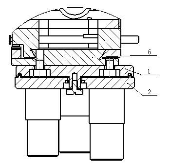
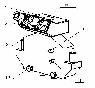
[0015] as attached figure 1 , 2 , 3, 4, 5, and 6 show that the gas of the present invention includes an objective lens, a reflector group, a tube mirror, a combined image prism, a field lens, a lens group, an illumination system, and a separate viewing system formed by an eyepiece system according to an optical path. Field microscope, and a fast zoom mechanism assembled at the objective lens installation of the separated field microscope. Such as figure 1 , 2 In the present invention shown in the rapid zooming mechanism of the objective lens, wherein the upper plate 1 of the rapid zooming mechanism of the objective lens is fixed on the moving guide rail 6 separated from the objective lens with two mounting screws, and the objective lens 3 of different magnifications is installed on the lower rotating disk 2, in order to reduce the In this mechanical structure, the objective lens positioning surface of the lower turntable 2 is designed on the same horizontal plane, and two i...


PUM

PropertyMeasurementUnit
lengthaaaaaaaaaa
lengthaaaaaaaaaa

Abstract

The invention relates to an alignment observation device which is applied to an exposure machine, in particular to a field-splitting microscope for realizing a rapid zooming function of an object lens. The field-splitting microscope consists of an object lens rapid-zooming device, an object lens system, an eye lens system and the like. The field-splitting microscope has the beneficial effects that the original field-splitting microscope is taken as a prototype, the operating distance of the lens and the distance between an eye-point exit pupil position and a working face are unchanged, the distance between the object lens and a reflector is increased, an object lens rapid-zooming mechanism is additionally arranged at the mounting position of the object lens, and the rotation part of the zooming mechanism is set into the form that the object lens locating surfaces of a lower turntable are positioned on the same horizontal plane; optimization design is carried out on an illumination system, and illuminating light and imaging light in a new light path are independently propagated in the horizontal direction; a steering structure of the light path is changed from an upright shape to a turning shape; and an eye-distance adjusting structure for the lens is changed from a straight-pull light-splitting structure to a rotary light-splitting structure. By utilizing the field-splitting microscope, the rapid zooming function of the object lens can be realized in the case of switchover between coarse alignment and fine alignment.

Description

technical field [0001] The invention relates to an alignment and observation device applied to an exposure machine, in particular to a rapidly variable magnification separation field-of-view microscope with an objective lens. Background technique [0002] The objective lens rapid zoom separation field microscope is one of the core components of the lithography machine. This component is available in foreign lithography machines and is self-developed. It is not sold separately in the world and cannot be purchased in China. Although domestic lithography machines are currently equipped with a separate field-of-view microscope, the objective lens cannot achieve a fast zoom function when switching between coarse alignment and fine alignment. In this regard, most of the users have made a request that our exposure machine can be equipped with a separate field microscope with a fast zoom function of the objective lens. Professional microscope manufacturers do not research and produ...

Claims


Application Information

Patent Timeline
Patent Type & Authority Applications(China)
IPC IPC(8): G02B21/24G02B21/08G02B17/08G03F7/20
Inventor 李玉敏蒲继祖
Owner THE 45TH RES INST OF CETC
Learn More