Hydraulic cylinder and relative device thereof, hydraulic buffer system, excavator and concrete pump truck

A technology of hydraulic cylinders and buffer sleeves, applied in the field of hydraulic cylinders, can solve the problems of extremely high manufacturing precision requirements of buffer mechanisms, unusable hydraulic cylinders, and difficulty in meeting the requirements of manufacturing level, so as to facilitate the organization of production, avoid mechanical failures, and process easy effect

Active Publication Date: 2011-06-29
SANY HEAVY IND CO LTD (CN)
View PDF6 Cites 16 Cited by
  • Summary
  • Abstract
  • Description
  • Claims
  • Application Information

AI Technical Summary

Problems solved by technology

At this time, the large buffer sleeve 04 in the above-mentioned buffer mechanism needs to be repeatedly inserted into the buffer inner hole 07 at high speed, and the fit gap between the two is originally very small, and the piston rod 03 is very heavy. It is easy to tilt to one side; therefore, the hydraulic cylinder used in the above occasions is prone to failure of the buffer mechanism that the buffer sleeve 04 cannot be inserted into the buffer inner hole 07, resulting in the failure of the entire hydraulic cylinder.
[0007] Another key problem of the above-mentioned buffer mechanism is that the outer diameter of the large buffer sleeve 04 must precisely match the inner diameter of the buffer inner hole 07, otherwise it cannot be realized Buffering effect; this results in extremely high manufacturing precision requirements for the buffer mechanism, and the manufacturing level of general manufacturers is difficult to meet the requirements
Due to the above-mentioned high requirements for manufacturing precision, hydraulic cylinders with large strokes and large bores have become a bottleneck in the production of excavators and other construction machinery, which seriously limits the production capacity of various downstream manufacturers.

Method used


Image

  • Hydraulic cylinder and relative device thereof, hydraulic buffer system, excavator and concrete pump truck
  • Hydraulic cylinder and relative device thereof, hydraulic buffer system, excavator and concrete pump truck
  • Hydraulic cylinder and relative device thereof, hydraulic buffer system, excavator and concrete pump truck

Examples


Embodiment Construction

[0063] In order to enable those skilled in the art to better understand the technical solution of the present invention, the present invention will be further described in detail below in conjunction with the accompanying drawings and specific embodiments.

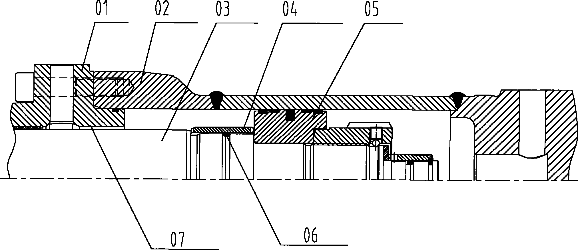
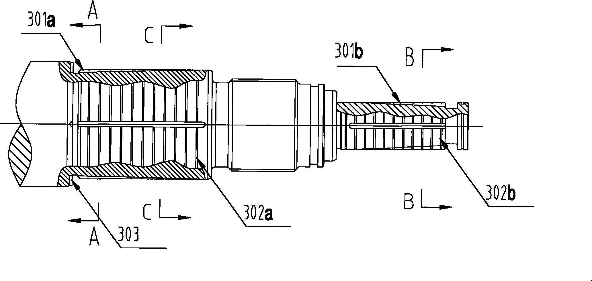
[0064] Please refer to Figure 2 to Figure 11 In the first specific embodiment, it includes a rod chamber end cover 1, a cylinder barrel 2, a piston rod 3, a piston 6 and a rodless chamber end cover 12, and the rod chamber end cover 1 is provided with an oil passage B, and the rodless The cavity end cover 12 is provided with an oil passage A, the piston rod 3 and the piston 6 divide the inner cavity of the hydraulic cylinder 2 into a rod chamber and a rodless chamber, and the oil passage B and the oil passage A are connected with the oil passage of the hydraulic system. Similar, they are all axial oil passages opened on the hydraulic cylinder. The oil passage B includes the oil passage hole opened on the rod chamber end c...


PUM


Abstract

The invention discloses a hydraulic cylinder which comprises a rod cavity end cover (1), a cylinder barrel (2), a piston rod (3), a piston (6) and a rodless cavity end cover (12), wherein an oil duct (B) is arranged on the rod cavity end cover (1); an oil duct (A) is arranged on the rodless cavity end cover (12); and the inner cavity of the hydraulic cylinder barrel (2) is divided into a rod cavity and a rodless cavity through the piston rod (3) and the piston (6). The hydraulic cylinder disclosed by the invention is characterized in that at least a buffer jacket is arranged on the piston rod (3); the buffer jacket comprises a first buffer jacket (4) and / or a second buffer jacket (11); the buffer jackets (4) and (11) can make an axial slide along the piston rod (3); and axial throttle oil ducts (301a) and (301b) are arranged between the buffer jackets (4) and (11) and the piston rod (3).

Description

technical field [0001] The invention relates to the field of hydraulic technology, in particular to a hydraulic oil cylinder. The invention also provides a hydraulic buffer system, an excavator and a concrete pump truck used for the hydraulic oil cylinder. Background technique [0002] The hydraulic cylinder is a widely used part in construction machinery. During its working process, the piston needs to reciprocate continuously. When the piston rod extends to the limit position, the end face of the piston will have a great impact on the end cover, which may cause damage to the hydraulic cylinder. For this reason, it is necessary to set a buffer device at this position to avoid damage to the hydraulic cylinder due to the above-mentioned impact. [0003] Existing buffer devices vary greatly depending on the application occasion and size of the hydraulic cylinder. Small oil cylinders can directly use compression springs as buffer devices. However, for hydraulic cylinders wit...

Claims


Application Information

Patent Timeline
Patent Type & Authority Applications(China)
IPC IPC(8): F15B15/14F15B15/20F15B15/22
CPCF04B1/00F15B15/222
Inventor 易小刚刘永东陈兵兵
Owner SANY HEAVY IND CO LTD (CN)
Why Eureka
Try Eureka