Rotor fluid generator and generating method
A technology of rotor fluid and generator, applied in the direction of rotary piston engine, rotary or oscillating piston engine, machine/engine, etc., can solve the problem of inability to achieve power generation, and achieve the effect of expanding applications and types, and simple structure
- Summary
- Abstract
- Description
- Claims
- Application Information
AI Technical Summary
Problems solved by technology
Method used
Image
Examples
Embodiment 1
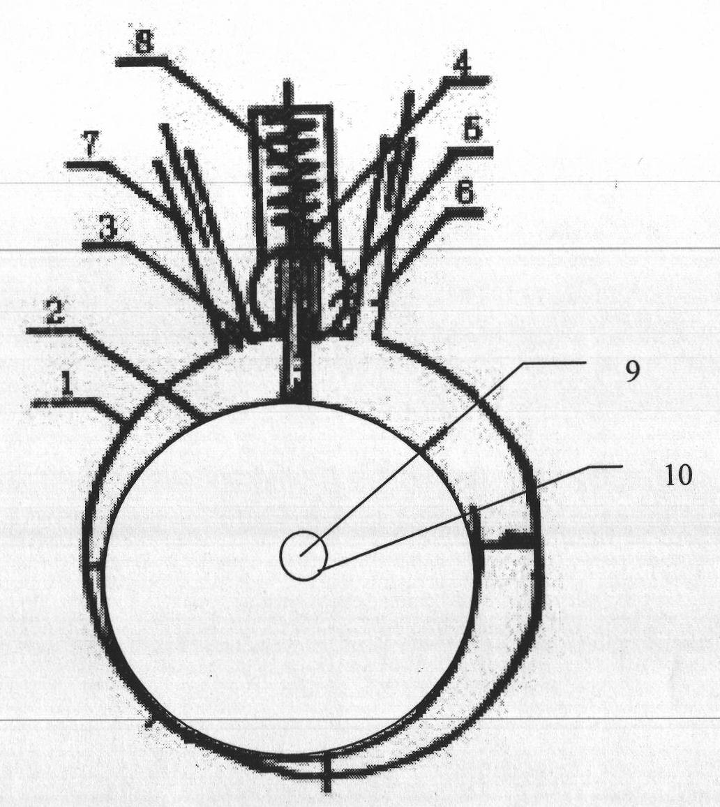
[0060] Embodiment 1: Schematic diagram of the structure of the eccentric rotor generator
[0061] Such as figure 1 As shown, the cylinder body 1 and the rolling rotor 2 are circular, the outer diameter of the rolling rotor 2 is smaller than the inner diameter of the cylinder body 1, and the rolling rotor 2 is arranged inside the cylinder body 1, and a rotating shaft 9 is arranged on the rolling rotor 2, The rotating shaft is an eccentric rotating shaft, and the rolling rotor 2 can rotate with the eccentric rotating shaft 9 as the center of a circle. When the rolling rotor rotates, at least a part of the outer wall of the rolling rotor is kept tangent to the inner wall of the cylinder body, and a slider is arranged on the cylinder body. 4. The slider 4 is provided with a spring 9. The slider 4 divides the cavity of the rolling rotor and the cylinder body into two cavities. The cylinder body is provided with a fluid inlet 7 and a fluid outlet 6. After the fluid enters through th...
Embodiment 2
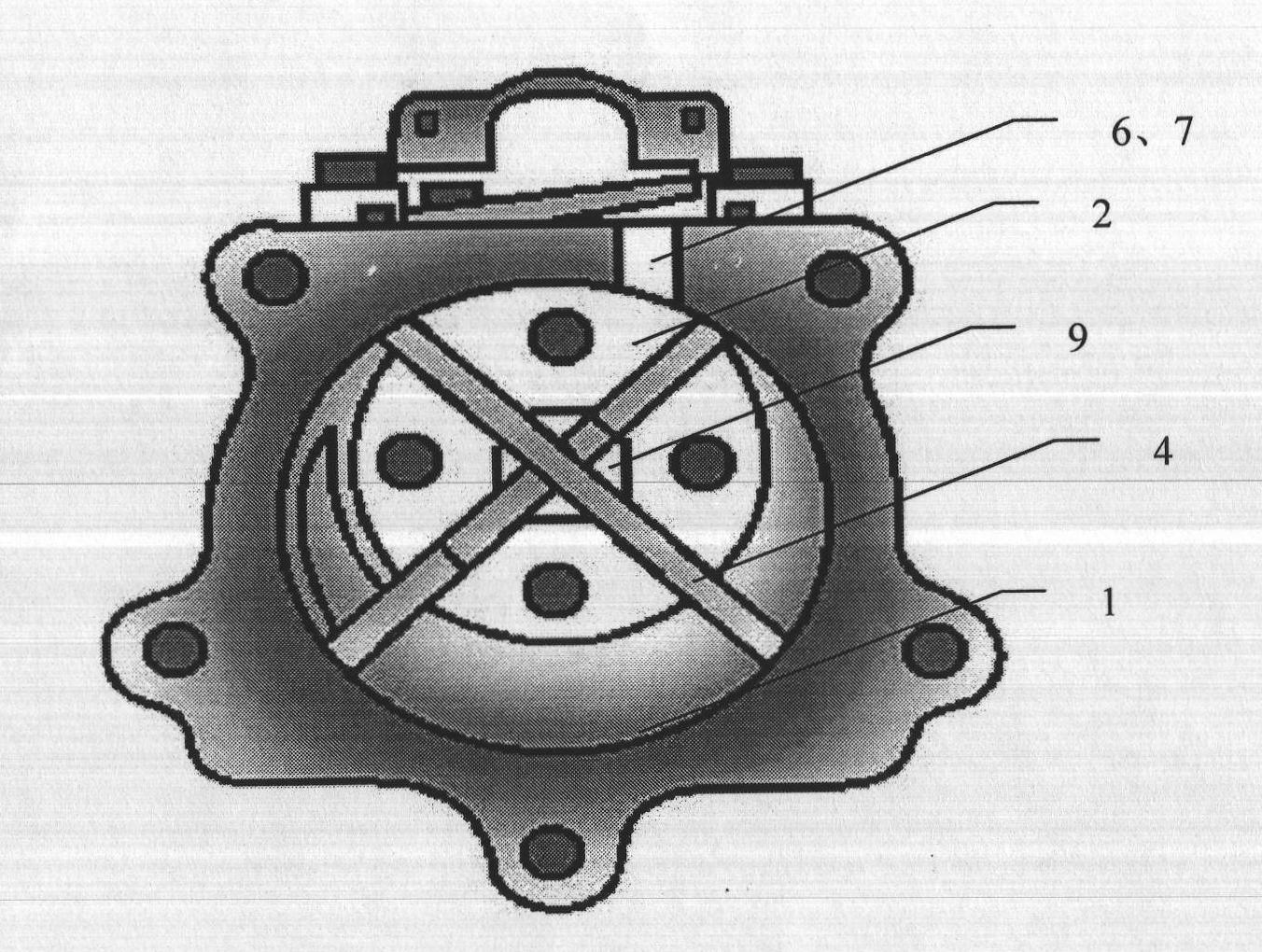
[0062] Embodiment 2: Schematic diagram of the through-slide fluid rotor generator
[0063] Such as figure 1 As shown, the cylinder body 1 and the rolling rotor 2 are circular, the outer diameter of the rolling rotor 2 is smaller than the inner diameter of the cylinder body 1, and the rolling rotor 2 is arranged inside the cylinder body 1, and a rotating shaft 9 is arranged on the rolling rotor 2, The rolling rotor 2 rotates with the rotating shaft 9 as the center of a circle. When the rolling rotor 2 rotates, at least a part of the outer wall of the rolling rotor is kept tangent to the inner wall of the cylinder body. There are two slides 4 on the chute. The slides 4 divide the cavity of the rolling rotor and the cylinder into four cavities. The cylinder is provided with a fluid inlet 7 and a fluid outlet 6. The fluid passes through the fluid After the inlet enters, it starts to go through multiple cavities composed of rolling rotors, cylinder inner walls, and sliders to cont...
Embodiment 3
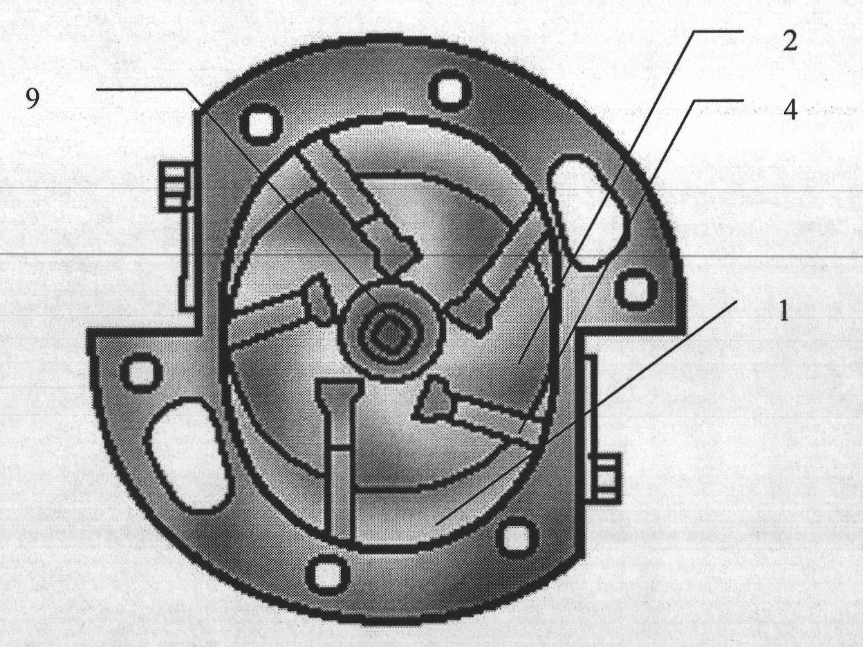
[0064] Embodiment 3: Double working cavity slider fluid rotor generator
[0065] Such as image 3 As shown, the cylinder body 1 is a partial circle, the rolling rotor 2 is circular, the outer diameter of the rolling rotor 2 is smaller than the inner diameter of the cylinder body 1, and the rolling rotor 2 is arranged inside the cylinder body 1, and the A rotating shaft 9, the rolling rotor 2 rotates with the rotating shaft 9 as the center of a circle, while the rolling rotor 2 rotates, the outer wall of the rolling rotor is kept tangent to at least a part of the inner wall of the cylinder body, and five slide grooves are arranged on the cylinder body, Five sliders 4 are arranged on the chute, and the slider 4 divides the cavity of the rolling rotor and the cylinder body into five cavities. The cylinder body is provided with a fluid inlet 7 and a fluid outlet 6, and the fluid enters through the fluid inlet. Afterwards, it begins to continuously expand and work through multiple...
PUM
 Abstract
Description
Claims
Application Information
 - R&D
- Intellectual Property
- Life Sciences
- Materials
- Tech Scout
- Unparalleled Data Quality
- Higher Quality Content
- 60% Fewer Hallucinations
Browse by: Latest US Patents, China's latest patents, Technical Efficacy Thesaurus, Application Domain, Technology Topic, Popular Technical Reports.
© 2025 PatSnap. All rights reserved.Legal|Privacy policy|Modern Slavery Act Transparency Statement|Sitemap|About US| Contact US: help@patsnap.com


