
Piston generator and power generation method

A generator and generator rotor technology, applied in reciprocating piston engines, variable capacity engines, machines/engines, etc., can solve problems such as low power generation efficiency and thermal energy loss, avoid thermal energy loss, improve efficiency, expand The effect of the form of energy use

Inactive Publication Date: 2016-08-03
BEIJING WISWORD HI TECH
View PDF4 Cites 0 Cited by
  • Summary
  • Abstract
  • Description
  • Claims
  • Application Information

AI Technical Summary

Problems solved by technology

Due to the need to condense the steam, a large amount of heat energy is lost in the condensation process, making the power generation efficiency not high

Method used


Image

  • Piston generator and power generation method
  • Piston generator and power generation method
  • Piston generator and power generation method

Examples


Embodiment 1

[0045] Embodiment 1: Basic structure of reciprocating piston generator without crosshead

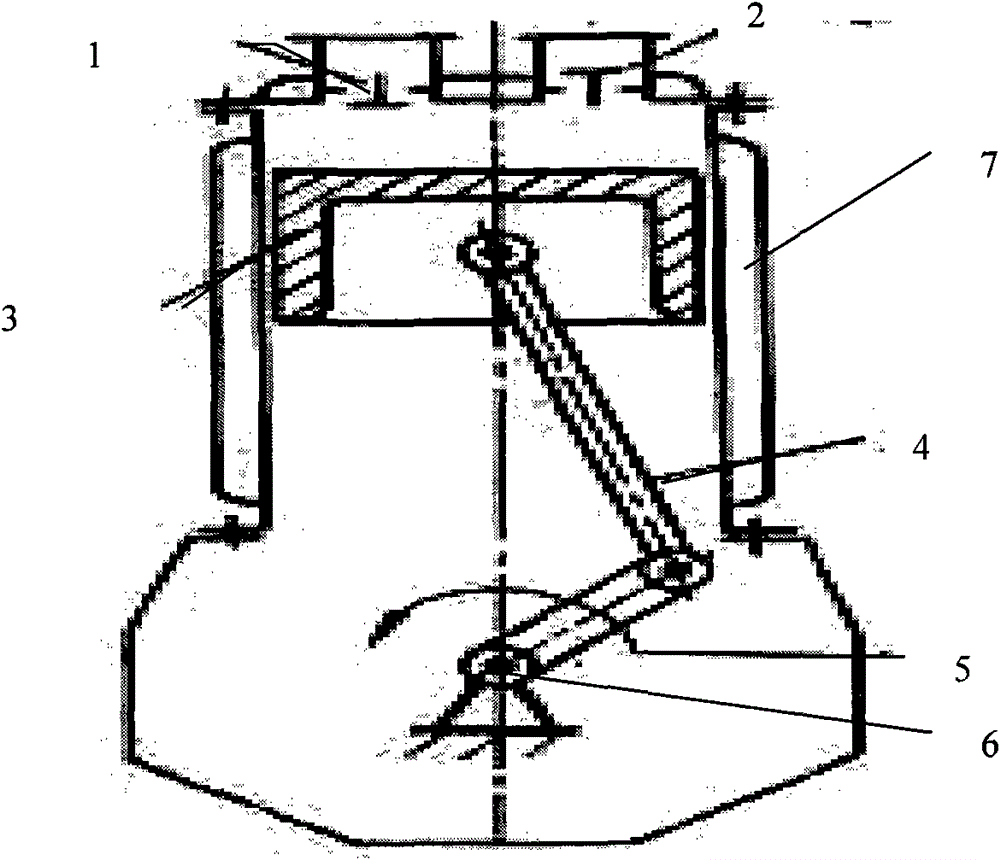
[0046] Such as figure 1 As shown, the piston 3 is arranged in the cylinder body 7, the inlet 1 and the outlet 2 of the fluid are arranged on the top of the piston, the piston 3 is connected with the rotor 6 of the generator through the connecting rod 4 and the crank 5, and the fluid enters from the fluid inlet and then the Expansion works, pushes the piston 3 to move, and the connecting rod and crank convert the reciprocating motion of the piston into rotation, realize the drive of the generator rotor, and realize the conversion of the kinetic energy of the fluid into electric energy.

Embodiment 2

[0047] Embodiment 2: Generator with reciprocating piston compressor structure driven by turntable

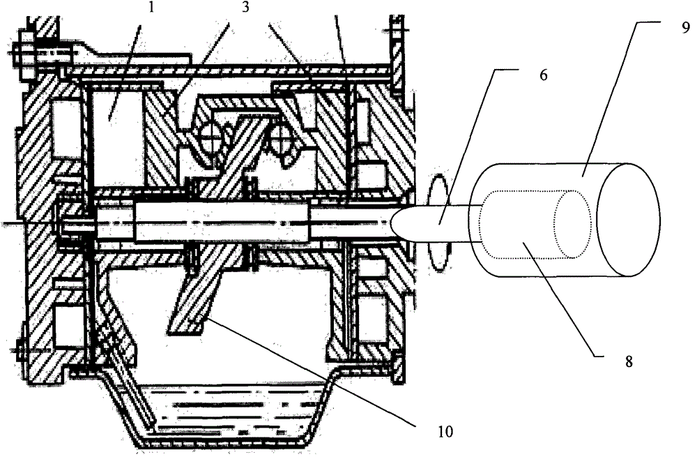
[0048] Such as figure 1 As shown, there are two pistons 3 and two cylinders 7 in this example, and the two pistons are connected by a turntable 10, and the two pistons drive the generator rotor 8 through the drive mechanism, and the generator rotor 8 is connected to the The stators around it create motion against each other, which converts fluid motion energy into electrical energy.

[0049] Liquid, gas, etc. or a mixture of liquid and gas can be used to generate electricity, so that the waste heat and pressure can be fully utilized, or supplemented by solar energy, shallow surface thermal energy, and traditional energy.

Embodiment 3

[0050] Embodiment 3: Counter-moving reciprocating piston generator

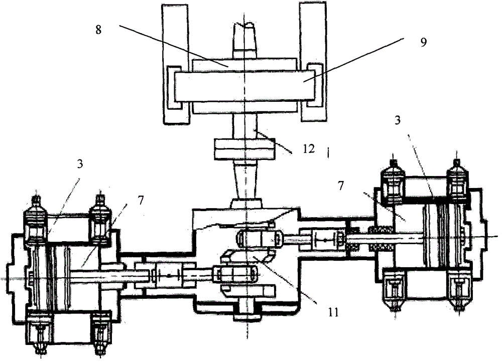
[0051] Such as image 3 As shown, this example is a horizontal structure, and the cylinders 7 are horizontally arranged on both sides of the crankshaft 11. The structure that moves toward or away from the two rows at the same time is called a counter-moving type, and the arrangement of the two cylinders 7 and the two pistons 3 facing the back On both sides of the generator, the cylinders are jointly connected with a drive shaft 11, the generator rotor 8 is set on the drive shaft, and the stator 9 of the generator is set around it, and the fluid flows from the ports and ports on the two cylinders. The outlet expands inside the cylinder and works, driving the piston in the cylinder to reciprocate. The driving mechanism converts the reciprocating motion into rotation and drives the generator rotor installed on the rotating shaft, thereby converting the kinetic energy of the fluid into electrical energy.


PUM


Abstract

The purpose of the present invention is to provide a fluid generator, which converts the kinetic energy of the fluid into mechanical energy by using a piston-cylinder structure, and then converts the mechanical energy into electrical energy through the movement of the stator and rotor; adopts a fluid that flows into the cylinder, through Expansion work is performed inside the cylinder to push the cylinder. The cylinder is connected to the generator rotor through the drive mechanism to drive the generator rotor. The generator rotor and the stator move with each other to convert the operating energy of the fluid into electrical energy. Another object of the present invention is to provide a method of converting fluid motion energy into electrical energy. The present invention is especially suitable for small power generation equipment, which can realize various power generation of 1w-200kw, preferably 0.1kw-30kw; it is suitable for "low-grade heat energy" utilizing solar energy, waste heat, waste pressure and geothermal energy Power generation, and suitable for sampling low-temperature organic working medium to achieve power generation, especially the use of organic Wolfken cycle to achieve power generation.

Description

technical field [0001] The invention relates to power generation equipment, which can use fluid to generate power, in particular to a device and method for generating power by sampling gas from a piston cylinder. Background technique [0002] The existing power generation technology mainly uses steam as the working medium to generate electricity. The main working medium is water. The nozzles are set on the stator without movement, and the blades are set on the rotor. The steam injected by the nozzles drives the blades to rotate and generate electricity. The existing technology is mainly generator sets above 100KW, and there is no suitable unit for miniaturization. [0003] The Rankine cycle (ORC) generator set using low-temperature organic matter is suitable for low-temperature heat sources and small-scale power generation, but it is mainly to miniaturize the existing large-scale steam power generation equipment, and its nozzle and blade settings are the same as those of lar...

Claims


Application Information

Patent Timeline
Patent Type & Authority Patents(China)
IPC IPC(8): F01B23/10F01B1/00F03C1/00
Inventor 李建民
Owner BEIJING WISWORD HI TECH
Learn More