


Quick Research
Generate reliable direction feasibility study reports for your R&D in just a few steps.

Technical Q&A
Discover and master advanced knowledge NOW. Basics, ideas, possibilities, all at once.

Find Solutions
As an expert in R&D theories, this can generate solutions to your technical problems instantly.

Evaluate Feasibility
Analyze your overall solution with one click, know your potential R&D risks in advance.

Monitor Landscape
Get weekly tech updates, stay abreast of the latest tech innovations and key insights.
Collecting chamber and method of production
A collecting chamber and collecting cavity technology, which is applied in radial flow pumps, parts of pumping devices for elastic fluids, liquid fuel engines, etc., can solve the problems of complicated casting components and high cost, and save space Effect
- Summary
- Abstract
- Description
- Claims
- Application Information
AI Technical Summary
Problems solved by technology
Method used
Image

Examples
Embodiment Construction
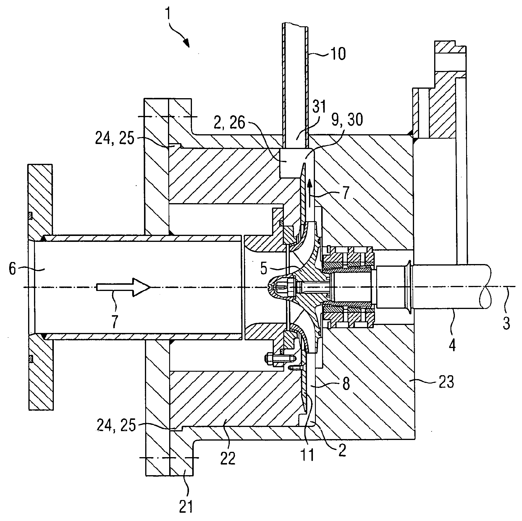
[0034] figure 1In a longitudinal sectional view, a part of a compressor 1 is shown, which has a collecting chamber 2 according to the invention, which extends in the circumferential direction around the machine axis 3 . The compressor 1 has a rotor 4 , at the end shown of which is arranged an impeller 5 (compression stage of the centrifugal compressor), which forms the free end of the shaft of the rotor 4 . The impeller 5 is axially flowed by the fluid 7 via the inflow means 6 and conveys the compressed fluid radially outwards into the peripheral chamber 8 . After a further 90° deflection 9, the fluid 7 flows from the peripheral chamber 8 into the collecting chamber 2, collects there, and enters the subsequent diffuser 10 (deflected in the circumferential direction) in a manner not shown separately. location shown).
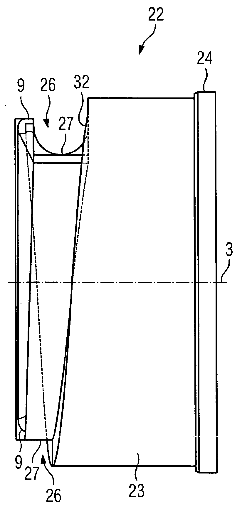
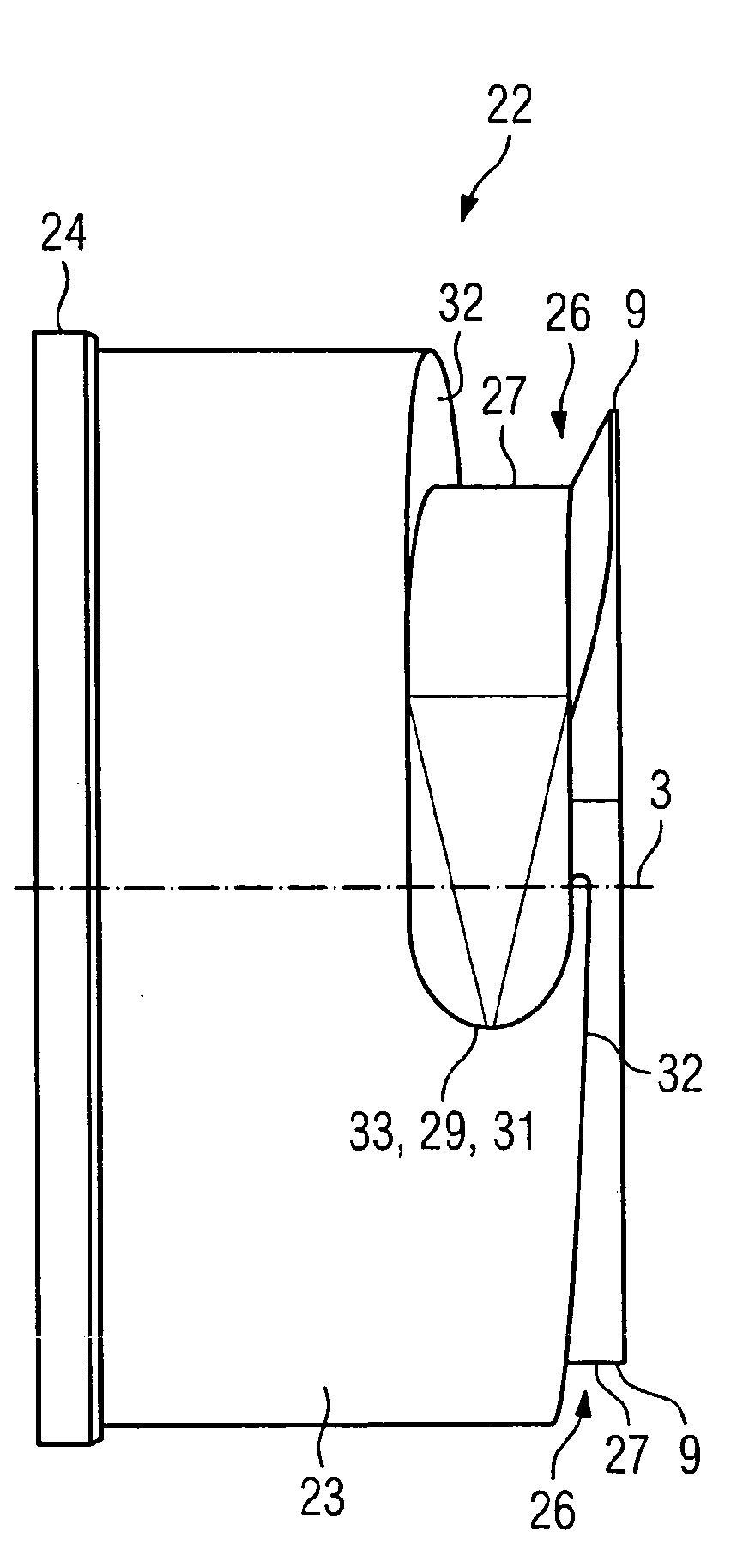
[0035] The collecting chamber 2 is formed by an outer housing part 21 and a contour insert 22 . The slot in the housing part 21 into which the profile insert ...
PUM
 Abstract
Description
Claims
Application Information
 - R&D Engineer
- R&D Manager
- IP Professional
- Industry Leading Data Capabilities
- Powerful AI technology
- Patent DNA Extraction
Browse by: Latest US Patents, China's latest patents, Technical Efficacy Thesaurus, Application Domain, Technology Topic, Popular Technical Reports.
© 2024 PatSnap. All rights reserved.Legal|Privacy policy|Modern Slavery Act Transparency Statement|Sitemap|About US| Contact US: help@patsnap.com