
Clothes dryer

A technology for drying machines and clothes, which is applied to clothes dryer equipment, household clothes dryers, washing machines with containers, etc., can solve the problems of conflict between the reduction of electric power consumption and the like, and achieve the effect of saving electric power consumption.

Active Publication Date: 2011-06-22
TOSHIBA LIFESTYLE PROD & SERVICES CORP
View PDF1 Cites 30 Cited by
  • Summary
  • Abstract
  • Description
  • Claims
  • Application Information

AI Technical Summary

Problems solved by technology

However, since the required time and reduction in electric power consumption conflict with each other, it is difficult to obtain a further balance between the reduction in required time and the reduction in electric power consumption

Method used


Image

  • Clothes dryer
  • Clothes dryer
  • Clothes dryer

Examples


no. 1 Embodiment

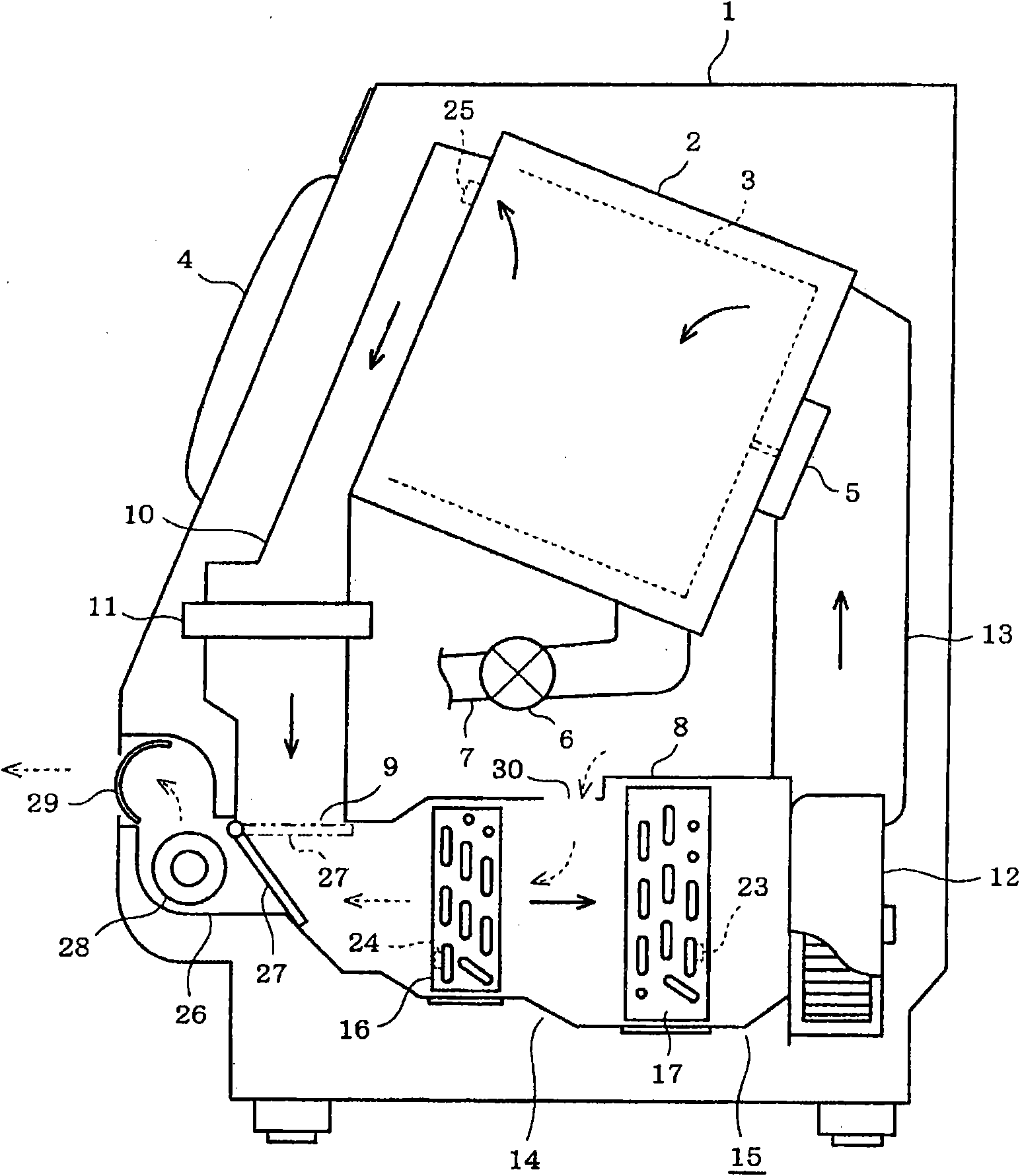
[0026] will refer to Figures 1 to 6 The first embodiment is described. refer to image 3 , shows a horizontal axis type drum washer-dryer applied with a laundry dryer. The washer-dryer comprises an outer case 1 housing a water tank 2 which also houses a rotary tank 3 like a drum. The water tank 2 and the rotary tank 3 constitute a washing tank in this embodiment. Although not shown in the drawings, the rotary tank 3 is porous, or has a large number of holes passing through the peripheral wall.

[0027] The water tank 2 and the rotary tank 3 are each formed in a cylindrical shape and each have an axis extending in the front-rear direction. The slots 2 and 3 are elastically supported by the suspension in an inclined state. The slots 2 and 3 each have a front opening. The outer case 1 has a front portion formed by a doorway (not shown) at the upper portion of the front. The access is closed or opened through the door 4 . The inlet and outlet are connected to the front open...


PUM


Abstract

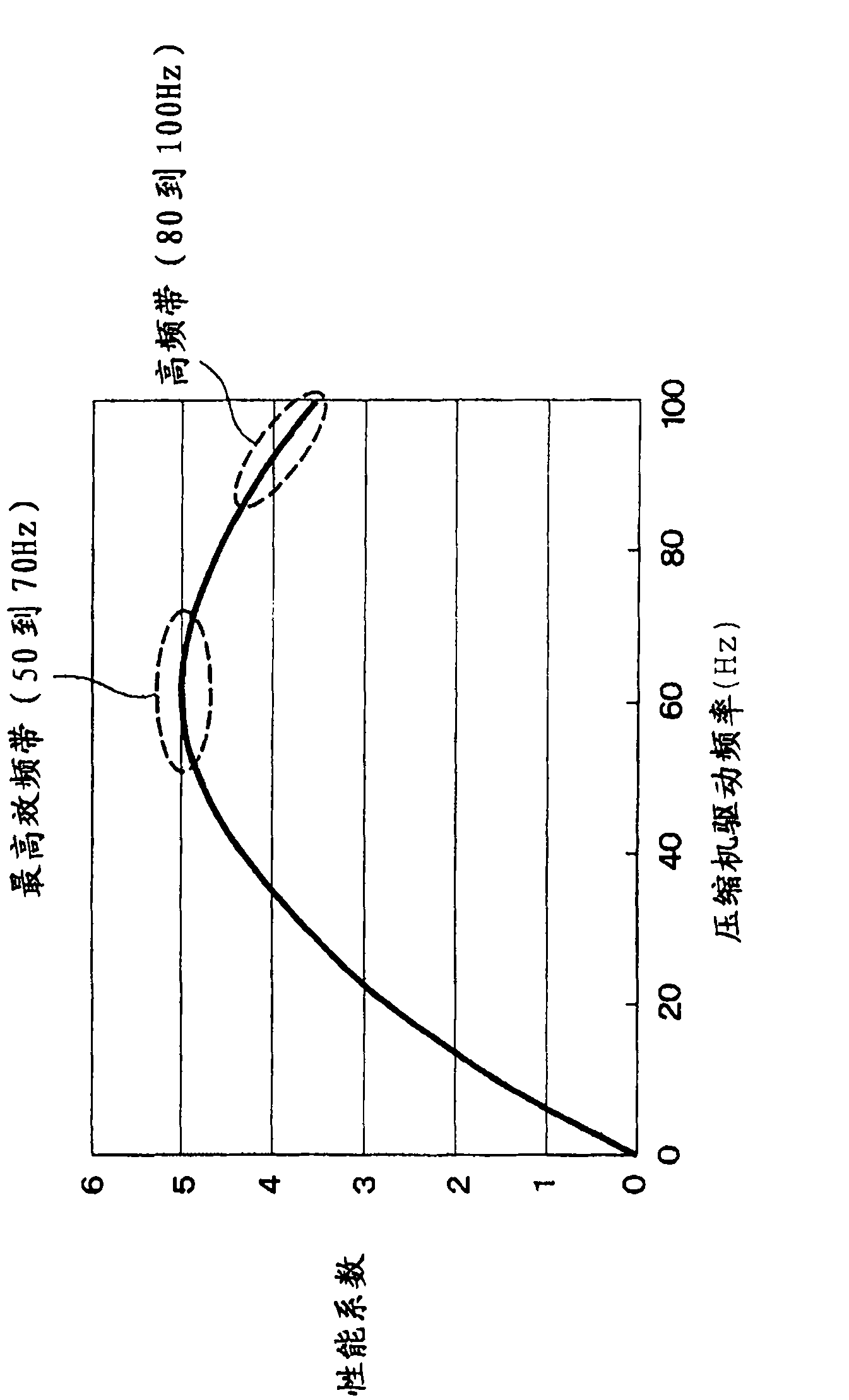
A clothes dryer provided with a washing tub, an air circulator, and a heat pump and drying laundry by operation of the air circulator and the heat pump. The rotational speed of a compressor is changed by controlling frequency, and the clothes dryer can be operated by selection of either a quick-drying mode for drying the laundry in a relatively short time by changing a drive frequency of the compressor or a saving mode for drying the laundry in a time longer than the time of the quick-drying mode. In the saving mode, the compressor is driven in a frequency band providing a high coefficient of performance.

Description

technical field [0001] The present invention relates to a laundry dryer for drying laundry by a heat pump. Background technique [0002] A laundry dryer equipped with a heat pump for drying laundry generally provides better drying performance and is attracting more and more attention because of the advantage of energy saving. Air in the washing tub containing the laundry is circulated through the airflow channel between the heat pump and the washing tub. The air in the washing tank is introduced into an evaporator and a condenser provided in an airflow passage and connected to a compressor and a throttle. The air flowing through the airflow channel is cooled and dehumidified by the evaporator and heated by the condenser. Then, the dehumidified and heated air in the airflow channel is sent to the washing tank. While thus circulating between the washing tub and the airflow channel, the air absorbs moisture from the laundry in the washing tub and is dehumidified in the airfl...

Claims


Application Information

Patent Timeline
Patent Type & Authority Applications(China)
IPC IPC(8): D06F25/00D06F58/02D06F58/28D06F58/46D06F58/48
CPCD06F58/28Y02B40/72D06F58/206D06F2058/287D06F2103/50D06F2105/26D06F2101/20D06F58/48D06F58/46D06F58/40Y02B40/00D06F2103/32D06F2105/52
Inventor 马越清辉西脇智佐久间勉
Owner TOSHIBA LIFESTYLE PROD & SERVICES CORP
Learn More