Sealing structure for pole post and intermediate cover of storage battery

A technology of sealing structure and storage battery, applied in the direction of structural parts, battery pack parts, circuits, etc., can solve the problems of low pass rate, pole scratches, and inability to assemble, so as to improve pass rate and production efficiency, and reduce position tolerance Requirements, design reasonable effect

Inactive Publication Date: 2011-06-22
浙江好途程节能科技有限公司
View PDF5 Cites 0 Cited by
  • Summary
  • Abstract
  • Description
  • Claims
  • Application Information

AI Technical Summary

Problems solved by technology

However, the sealing structure of the existing storage battery poles still has substantial defects. The reason is that there are multiple poles in the storage battery, especially for medium and large storage batteries. The tolerance of the shaft center of the output port of the cover pole is within 0.5mm, otherwise it will cause problems such as poor sealing or failure to assemble
In actual production, it is impossible to ensure that the pole is in the design position and within the tolerance range, that is, there is a very low pass rate and high production costs.
Although some manufacturers are forced to adjust the small-capacity poles, the poles are scratched and deformed after adjustment, resulting in reduced sealing performance and certain quality problems in the products.

Method used


Image

  • Sealing structure for pole post and intermediate cover of storage battery
  • Sealing structure for pole post and intermediate cover of storage battery
  • Sealing structure for pole post and intermediate cover of storage battery

Examples


Embodiment Construction

[0027] The following are specific embodiments of the present invention combined with the accompanying drawings to further describe the technical solutions of the present invention, but the present invention is not limited to these embodiments.

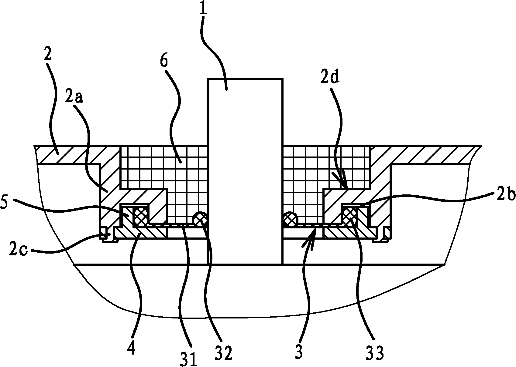
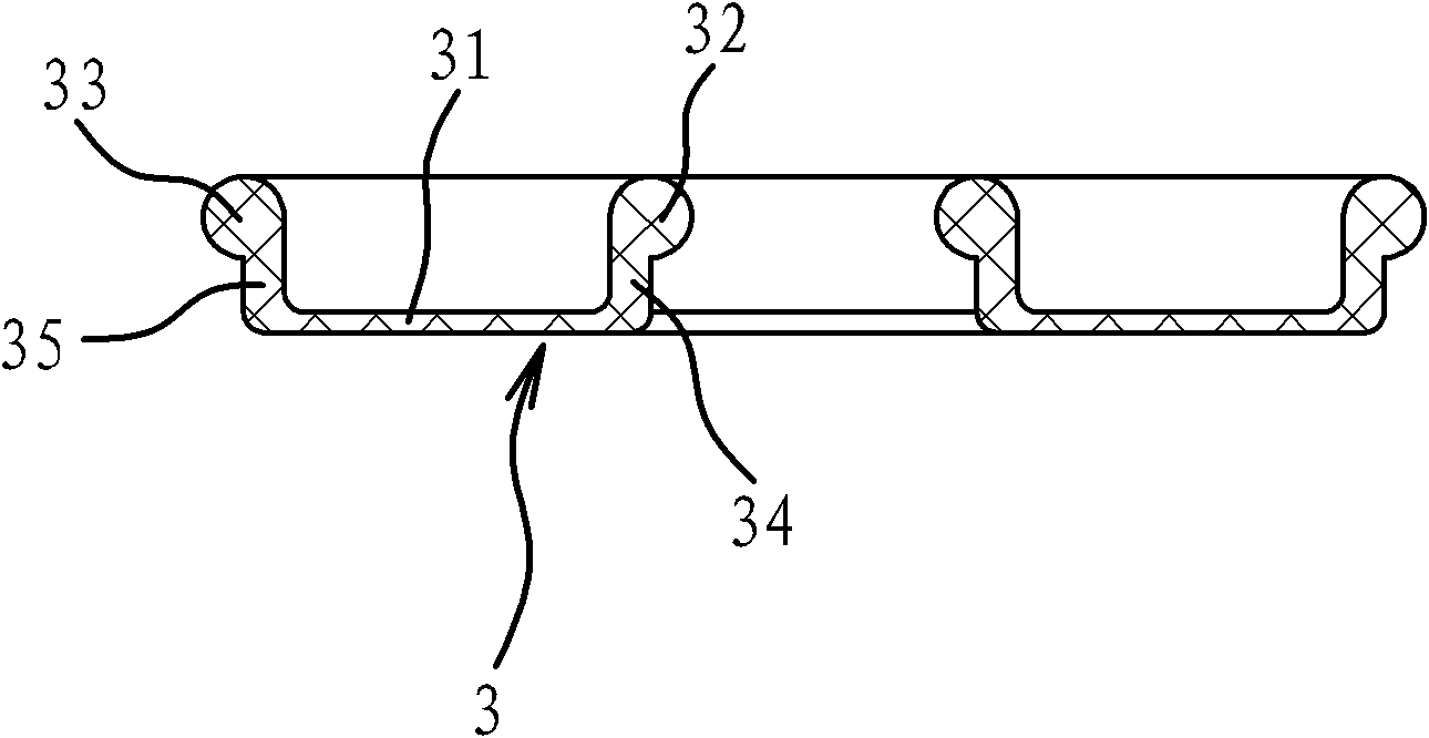
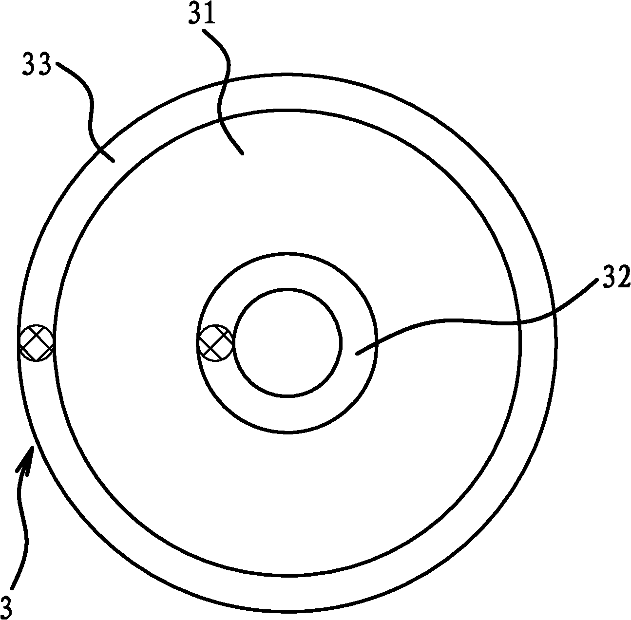
[0028] Such as figure 1 As shown, the battery includes a middle cover 2, a pole 1 and a sealing structure. The middle cover 2 has through holes corresponding to the pole 1 one to one, and the sealing structure also corresponds to the pole 1 one to one. The sealing structure of the pole 1 and the middle cover 2 includes a filling fixing member 6, a sealing member 3 and a fixing portion 2 a located at the edge of the through hole of the middle cover 2.

[0029] Specifically, such as figure 1 As shown, the ratio of the minimum value of the annular gap between the inner surface of the fixing portion 2a and the outer surface of the pole 1 to the diameter of the pole 1 is 1:2-20. The minimum value of the annular relief gap is directly related to...


PUM


Abstract

The invention provides a sealing structure for a pole post and an intermediate cover of a storage battery, belongs to the technical field of batteries, and solves the problem of poor sealing performance of the sealing structure of the pole post and the intermediate cover of the conventional storage battery. The sealing structure, with an improved structure, for the pole post and the intermediate cover of the storage battery comprises a fixing part positioned on the edge of a through hole of the intermediate cover, wherein a filling fixing piece and a sealing piece are arranged between the inside surface of the fixing part and the outside surface of the pole post; the sealing piece is positioned inside the filling fixing piece; the sealing piece comprises an annular sheet elastic part and a first sealing part which is positioned on the inner edge of the elastic part; the inside surface of the first sealing part is pressed against the outside surface of the pole post; the outer edge part of the elastic part is fixed to the fixing part of the intermediate cover; and annular seal is formed between the outer edge part of the elastic part and the fixing part of the intermediate cover. The sealing structure, with the improved structure, for the pole post and the intermediate cover of the storage battery has the advantages of reasonable design, simple structure and high sealing performance.

Description

Technical field [0001] The invention belongs to the technical field of batteries, and relates to a battery, in particular to a sealing structure of a battery pole and a middle cover. Background technique [0002] Storage battery is a kind of battery, also called secondary battery or energy storage battery. When the battery is working, the reactions on the two poles are all reversible reactions. Therefore, the charging method can be used to restore the active material of the two poles to the initial state, so that the battery can be regenerated, and the charging and discharging can be repeatedly used for multiple cycles. [0003] The battery pole connected to the external electrical connector protrudes from the battery cover, that is, the positive and negative poles pass through the through hole on the same battery cover. In this way, the sealing of the battery pole becomes a very important part of the battery manufacturing industry. technical problem. [0004] The existing sealing ...

Claims


Application Information

Patent Timeline
IPC IPC(8): H01M2/08
CPCY02E60/12Y02E60/10
Inventor 林子进
Owner 浙江好途程节能科技有限公司
Why Eureka
Try Eureka