Sealing structure of screw kiln

A technology of sealing structure and spiral kiln, which is applied in the field of machinery, can solve the problems of poor sealing effect and lower product quality, and achieve the effect of improving quality, avoiding air entry, and improving sealing effect

Active Publication Date: 2016-11-16
宜春天赐高新材料有限公司
View PDF5 Cites 0 Cited by
  • Summary
  • Abstract
  • Description
  • Claims
  • Application Information

AI Technical Summary

Problems solved by technology

[0004] In the magnesium silicide reaction device with this structure, the screw feeder is located at the feed end of the rotary kiln, and the screw discharger is located at the discharge end of the rotary kiln, and the screw feeder and the screw discharger are both arranged along the horizontal direction , that is, the inlet and outlet of the screw feeder are located at the same height, and the inlet and outlet of the screw feeder are also located at the same height. The setting of the screw feeder and the screw outlet in this way, There is a gap between the material in the screw feeder and the inner wall of the screw feeder, and there is a gap between the material in the screw feeder and the inner wall of the screw feeder. The screw feeder and the screw discharger The material in the container cannot isolate the contact between the rotary kiln and the outside world, and the sealing effect is poor, that is, some air will enter the interior of the rotary kiln, and the entry of oxygen will reduce the quality of the product

Method used


Image

  • Sealing structure of screw kiln
  • Sealing structure of screw kiln
  • Sealing structure of screw kiln

Examples


Embodiment Construction

[0026] The following are specific embodiments of the present invention and in conjunction with the accompanying drawings, the technical solutions of the present invention are further described, but the present invention is not limited to these embodiments.

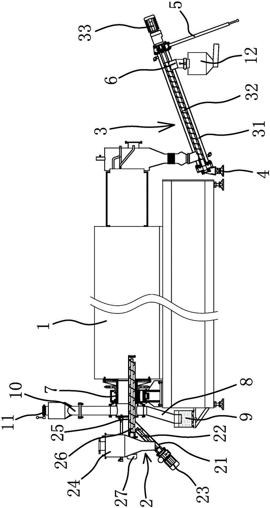
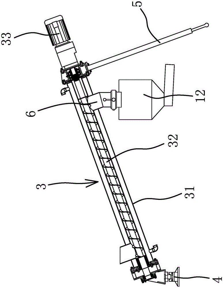
[0027] Such as figure 1 As shown, the spiral kiln includes a furnace tube 1, a feeder 2, a discharger 3 and a connecting cylinder 7. The feeder 2 is arranged at the feed end of the furnace tube 1, and the discharger 3 is arranged at the outlet of the furnace tube 1. At the material end, the feeder 2 and the discharger 3 are used as a sealing structure to seal the furnace tube 1, so that the two ends of the furnace tube 1 form a material seal.

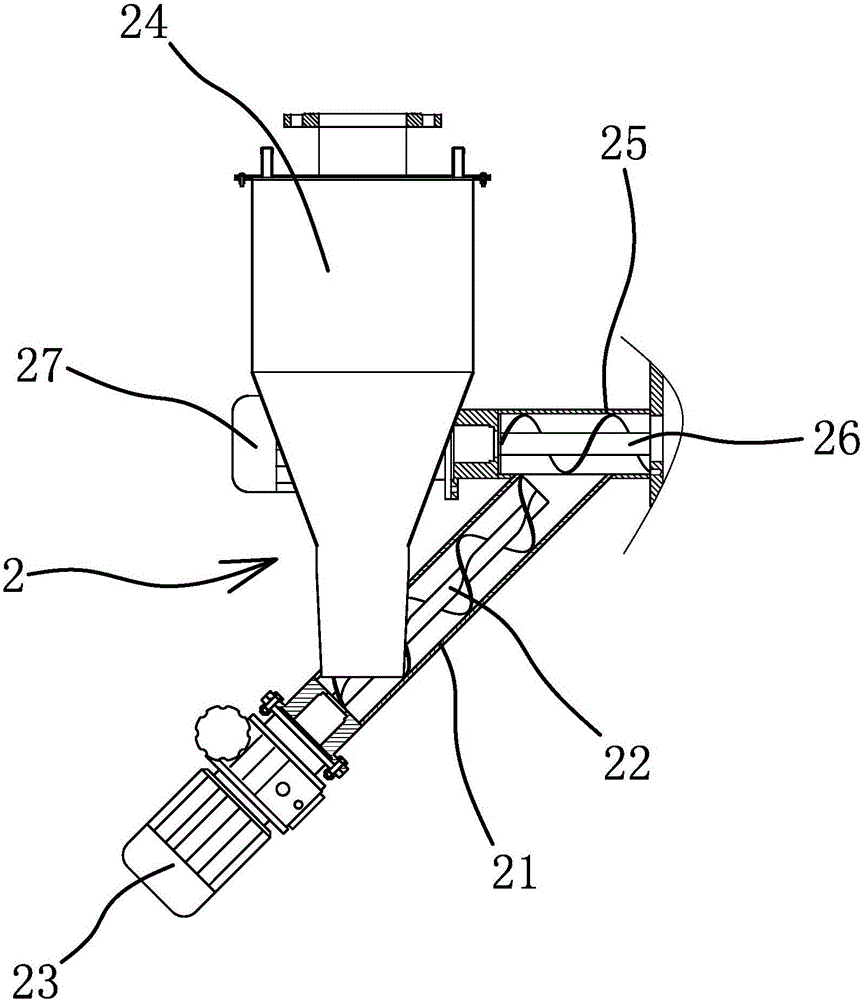
[0028] Such as figure 2 As shown, the feeder 2 includes a first conveying pipe 21 , a first screw rod 22 , a first driver 23 , a feeding bin 24 , a second conveying pipe 25 , a second screw rod 26 and a second driver 27 .

[0029] The first conveying pipe 21 is arranged obliquely...


PUM


Abstract

The invention provides a sealing structure of a screw kiln, belongs to the technical field of machinery, and solves the problem of poor sealing effect of a conventional screw kiln. The screw kiln comprises a furnace tube. The sealing structure comprises a feeder and a discharger, wherein the feeder is arranged at a feed end of the furnace tube; the discharger is arranged at a discharge end of the furnace tube; a feed opening of the feeder is located below a discharge opening of the feeder in the vertical direction; the discharge opening of the feeder is fixedly connected with the feed end of the furnace tube in a sealing way; a feed opening of the discharger is located below a discharge opening of the discharger in the vertical direction; and the feed opening of the discharger is fixedly connected with the discharge end of the furnace tube. The sealing structure has the advantage of improving the effect of the screw kiln.

Description

technical field [0001] The invention belongs to the technical field of machinery and relates to a sealing structure of a screw kiln. Background technique [0002] Rotary kiln refers to rotary calcining kiln, which belongs to the category of building materials equipment. Rotary kiln can be divided into cement kiln, metallurgical chemical kiln and lime kiln according to different materials. [0003] Existing rotary kilns, such as Chinese patent documents disclose an optimized magnesium silicide reaction device [application number: 201120160059.9; authorized announcement number: CN202116325U], the main body of which is a reactor composed of a rotary kiln. The mouth is provided with a screw feeder, and the screw feeder is connected with the feed bin and connected with the rotary kiln through a rotary joint; The feed preheating section, reaction section, and warming reaction section of the kiln are respectively equipped with heating mechanisms, and a screw discharger is connect...

Claims


Application Information

Patent Timeline
Patent Type & Authority Applications(China)
IPC IPC(8): F27B7/24F27B7/32
CPCF27B7/24F27B7/3205
Inventor 李正斌赵杰闫振忠
Owner 宜春天赐高新材料有限公司
Why Eureka
Try Eureka