Floating cylinder sleeve sealing structure

A technology of sealing structure and floating cylinder, which is applied to the sealing device of the engine, engine components, machine/engine, etc., to achieve the effect of tight sealing and elimination of influence

Inactive Publication Date: 2021-04-06
CHINA NORTH ENGINE INST TIANJIN
View PDF5 Cites 1 Cited by
  • Summary
  • Abstract
  • Description
  • Claims
  • Application Information

AI Technical Summary

Problems solved by technology

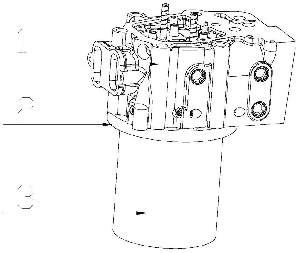
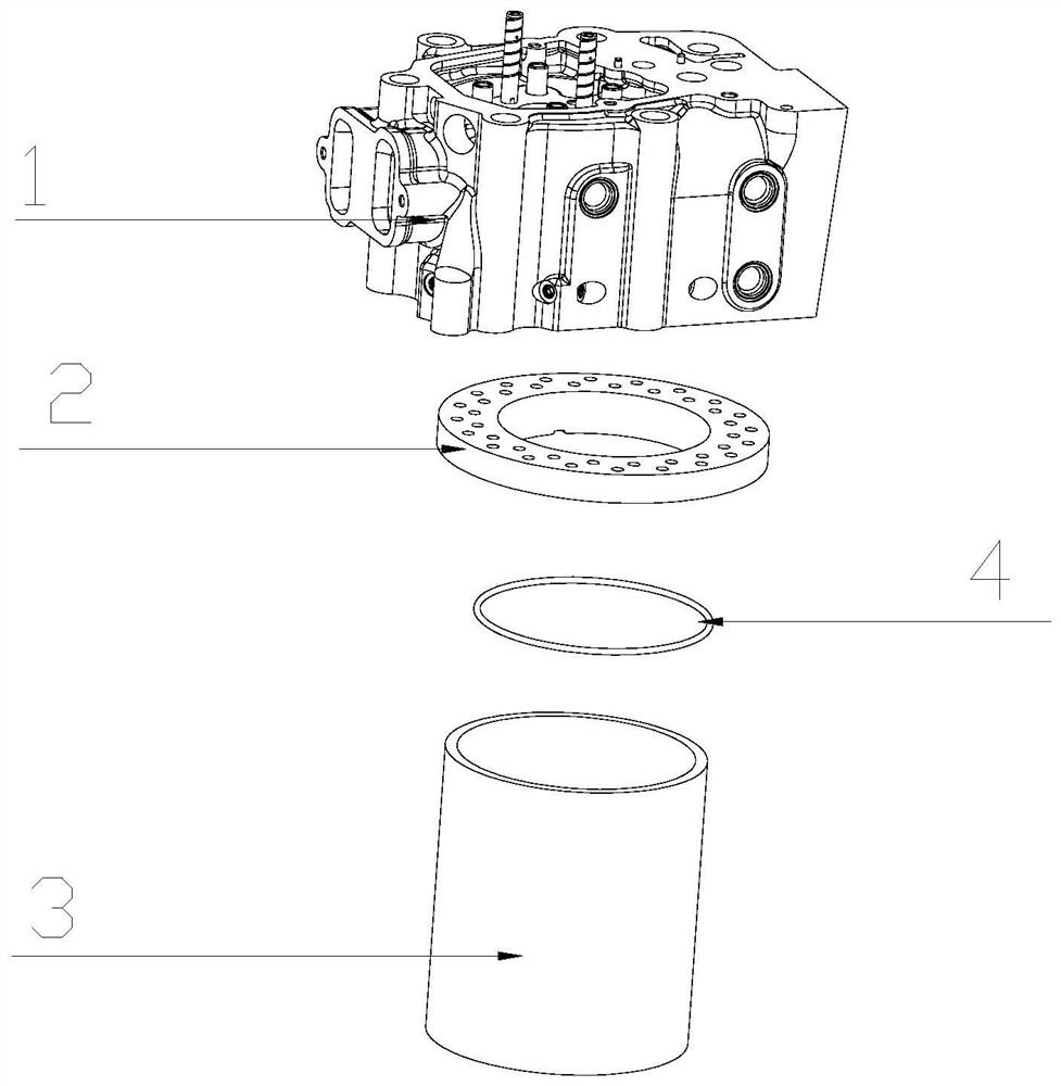
[0004] In view of this, the present invention aims to propose a floating cylinder liner sealing structure to solve the sealing problem between the cylinder head and the cylinder block of the floating cylinder liner test platform where the explosion pressure in the cylinder is below 15MPa

Method used


Image

  • Floating cylinder sleeve sealing structure
  • Floating cylinder sleeve sealing structure
  • Floating cylinder sleeve sealing structure

Examples


Embodiment Construction

[0021] It should be noted that, in the case of no conflict, the embodiments of the present invention and the features in the embodiments can be combined with each other.

[0022] In describing the present invention, it should be understood that the terms "center", "longitudinal", "transverse", "upper", "lower", "front", "rear", "left", "right", " The orientations or positional relationships indicated by "vertical", "horizontal", "top", "bottom", "inner" and "outer" are based on the orientations or positional relationships shown in the drawings, and are only for the convenience of describing the present invention and Simplified descriptions, rather than indicating or implying that the device or element referred to must have a particular orientation, be constructed and operate in a particular orientation, and thus should not be construed as limiting the invention. In addition, the terms "first", "second", etc. are used for descriptive purposes only, and should not be interpreted...


PUM


Abstract

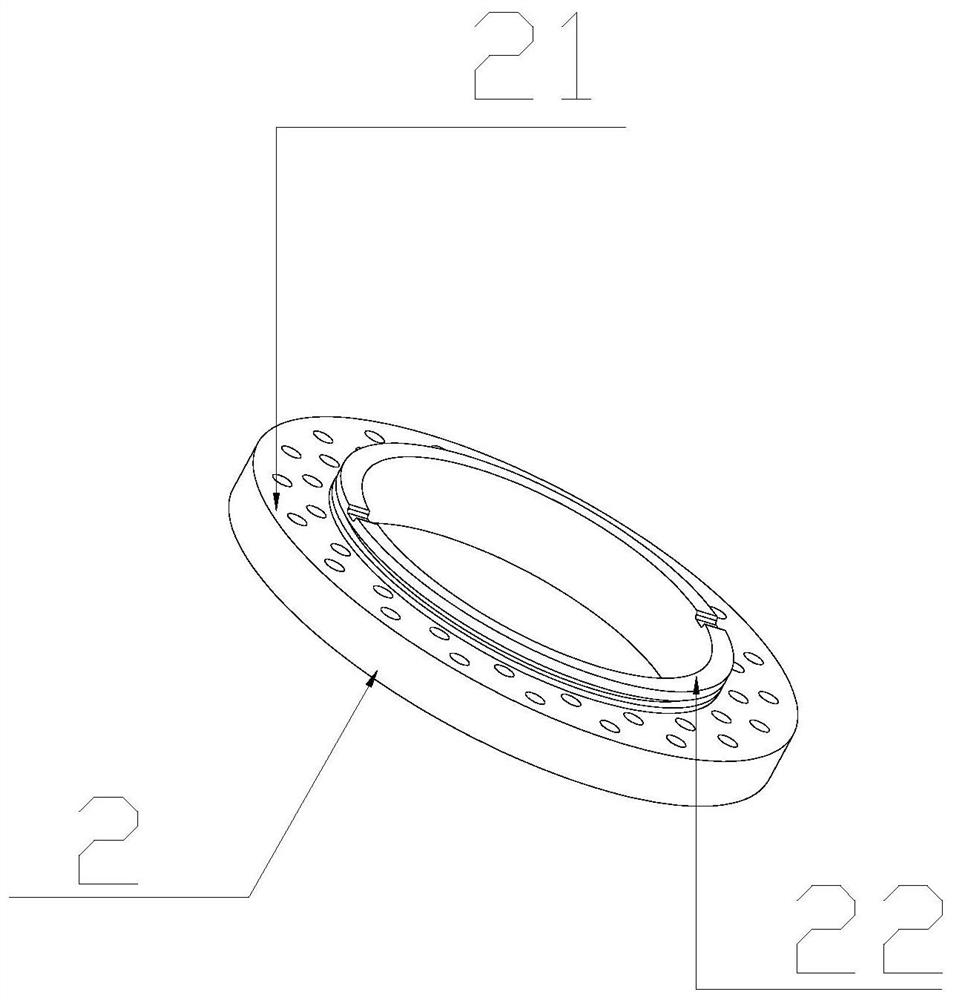
The invention provides a floating cylinder sleeve sealing structure which comprises a floating cylinder body, a sealing connecting piece, a floating cylinder sleeve, a sealing ring and a fixed connecting piece, the interior of the floating cylinder sleeve communicates with the interior of the floating cylinder body through a through hole, a plurality of first mounting holes are formed in the side wall of the upper end of the sealing connecting piece in the circumferential direction, and a plurality of second mounting holes are formed in the lower end of the floating cylinder body, one end of the fixed connecting piece is connected to the upper end of the sealing connecting piece in a clamped mode, the other end of the fixed connecting piece sequentially penetrates through the first installation hole and the second installation hole and then is fixedly connected to the lower end of the floating cylinder body, an annular groove is formed in the periphery of the lower end of the sealing connecting piece, and the sealing ring is connected into the annular groove in a sleeved mode, and the periphery of the lower end of the sealing connecting piece is sleeved with the inner ring of the floating cylinder sleeve, and the sealing ring is located in the floating cylinder sleeve. According to the floating cylinder sleeve sealing structure of the invention, the problem of sealing between the cylinder cover and the cylinder body of the floating cylinder sleeve test platform with the explosion pressure in the cylinder being 15 MPa or below is solved.

Description

technical field [0001] The invention belongs to the technical field of engine cylinder testing, in particular to a floating cylinder liner sealing structure. Background technique [0002] At present, the domestic floating cylinder liner test platform can test the explosion pressure in the cylinder within 10MPa, which cannot meet the test requirements of 13-22MPa for high-power engines, mainly due to the increase in the explosion pressure in the cylinder after the relative movement of the cylinder liner. Finally, the sealing problem between the cylinder head and the cylinder block is difficult to solve. [0003] At present, the main sealing methods are O-ring sealing and active sealing. The disadvantage of using O-ring sealing alone is that the sealing effect will decrease as the temperature in the cylinder increases, resulting in air leakage and inaccurate test data. . Active sealing is to use the method of replenishing air in the cylinder to achieve the balance of the amo...

Claims


Application Information

Patent Timeline
Patent Type & Authority Applications(China)
IPC IPC(8): F02F11/00
CPCF02F11/002
Inventor 钱志高王延荣郭昌明张伟
Owner CHINA NORTH ENGINE INST TIANJIN
Why Eureka
Try Eureka