
Pipette device

一种移液器、轴向移动的技术,应用在实验室器具、量管/吸液管、化学仪器和方法等方向,能够解决调整花费时间、无法调整采集量、调整花费工夫等问题,达到提高作业性的效果

Active Publication Date: 2011-06-22
FUKAE KASEI
View PDF6 Cites 9 Cited by
  • Summary
  • Abstract
  • Description
  • Claims
  • Application Information

AI Technical Summary

Problems solved by technology

[0003] However, in the above-mentioned existing pipette device, since the stroke amount per rotation of the adjustment handle is small, if the push rod does not rotate a considerable number of turns, it cannot be adjusted to the desired collection volume. issues such as time-consuming adjustments
In particular, when the amount of collection changes frequently, it takes time to adjust, and since the operability is poor, improvement is required in this point

Method used


Image

  • Pipette device
  • Pipette device
  • Pipette device

Examples


Embodiment 1

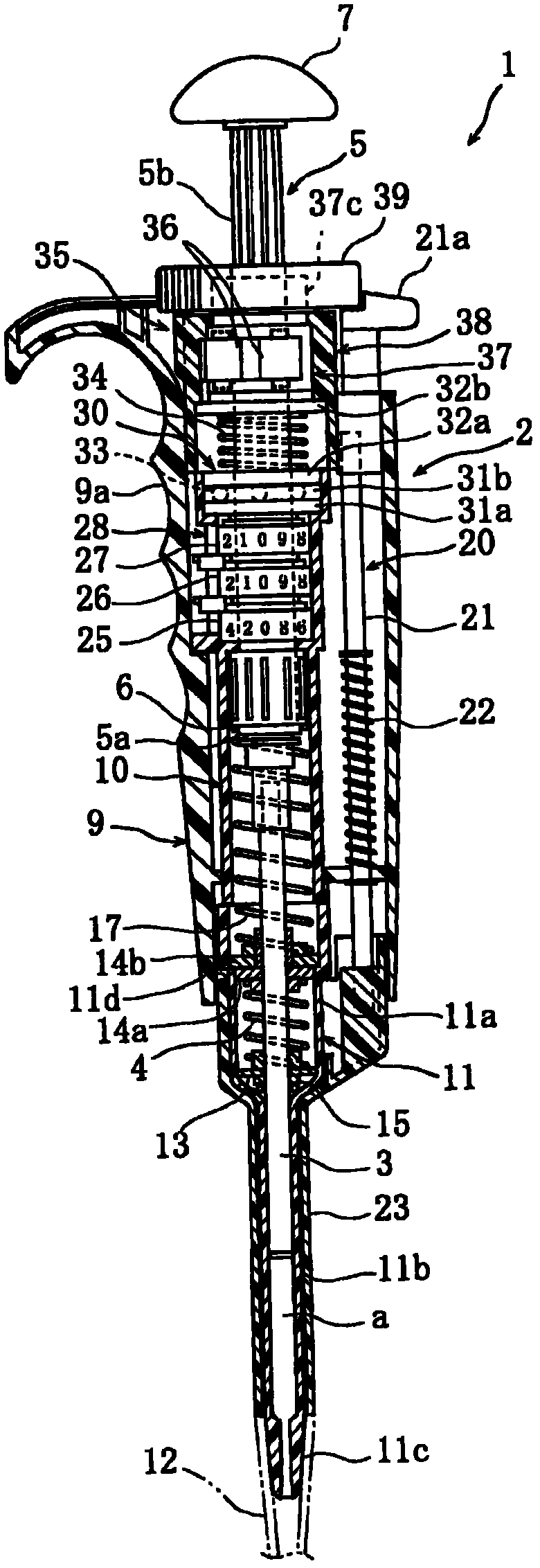
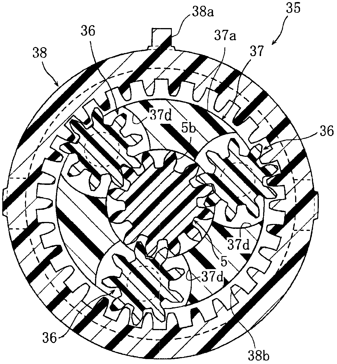
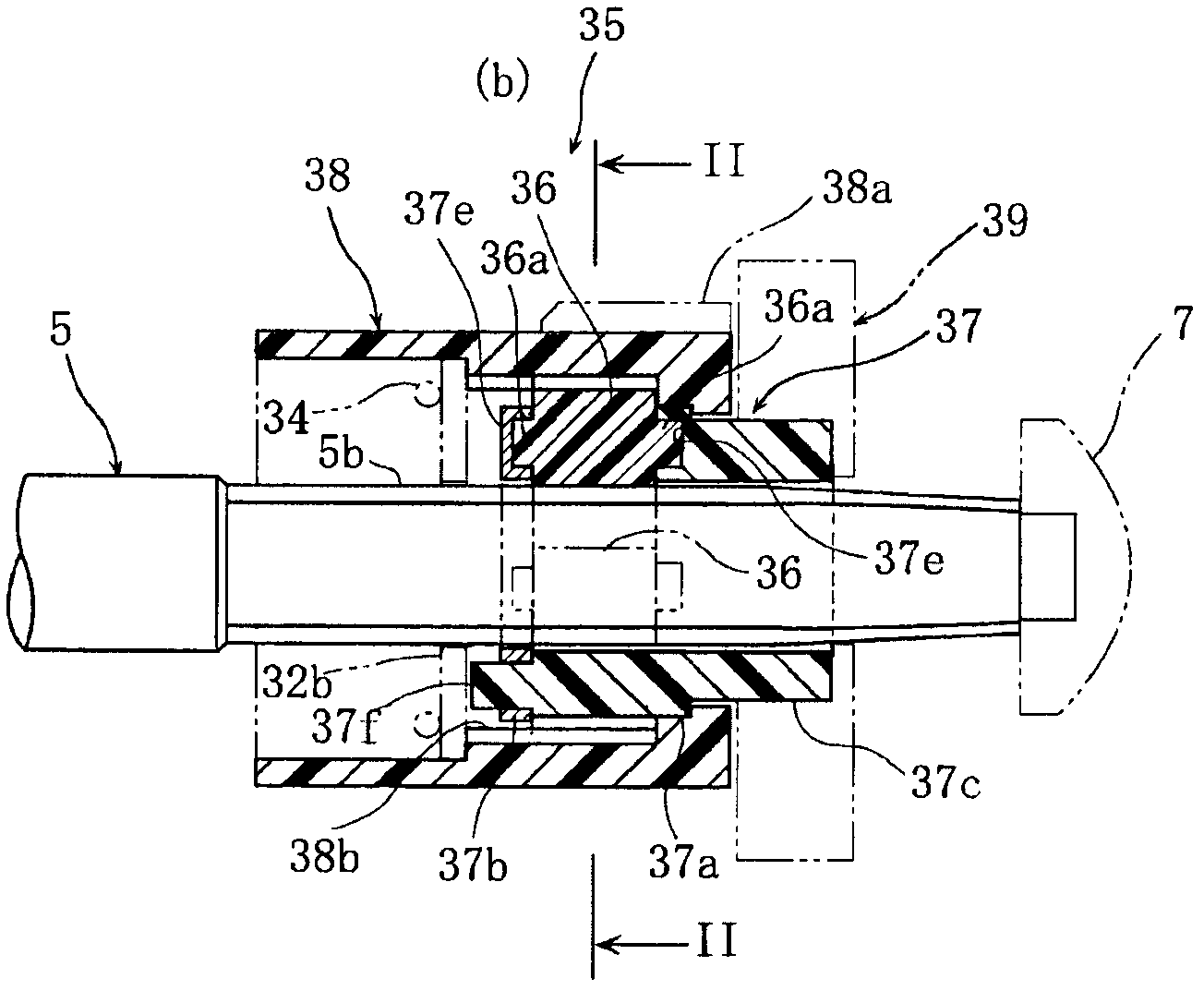
[0030] Figure 1 to Figure 10 It is a figure for explaining the pipette device of Example 1 of the present invention.

[0031] In the drawings, reference numeral 1 denotes a pipette device for quantitatively collecting a sample (liquid) used in inspection, analysis, or experiment.

[0032] The above-mentioned pipette device 1 includes: a pipette body 2 having a cylindrical portion a; a plunger 3 disposed in the cylindrical portion a so as to be movable in the axial direction, And the cylinder volume of the above-mentioned cylinder part a is changed; the push rod 5 is inserted into the above-mentioned pipette main body 2 in a rotatable and axially movable manner, and the above-mentioned plunger 3 is moved along the axis. and a nut 6 that is non-rotatably supported on the pipette body 2 and converts the rotation of the push rod 5 into the axial movement of the push rod 5 . In addition, the above-mentioned cylinder volume means the distance (stroke) by which the above-mentioned...


PUM


Abstract

There is provided a pipette device capable of adjusting a collection amount in a short time. A pipette device 1 adjusting a volume of a cylinder portion 'a' by the axial-direction movement of a plunger 3 caused by the rotation of a push rod 5 includes a speed increasing mechanism 35 provided between a pipette main body 2 and the push rod 5 and increasing a speed of input rotation to transmit the input rotation with the increased speed to the push rod 5.

Description

technical field [0001] The present invention relates to a pipette device for quantitatively collecting a sample (liquid) used in inspection, analysis, or experiment. Background technique [0002] In such a pipette device, a collection volume adjustment mechanism capable of finely adjusting the collection volume of liquid is provided. For example, the following is disclosed in Japanese Patent Laid-Open No. 6-210188. The plunger that changes the volume of the cylinder can be freely advanced and retracted in the cylindrical part of the pipette body, and the push rod that allows the plunger to advance and retreat is inserted into the pipette so that it can rotate and move in the axial direction. Inside the main body, a nut member to be engaged with the push rod is non-rotatably supported on the pipette main body. In addition, by rotating the adjustment knob fixed to the push rod, the push rod moves in the axial direction to adjust the stroke amount of the plunger. [0003] Ho...

Claims


Application Information

Patent Timeline
Patent Type & Authority Applications(China)
IPC IPC(8): B01L3/02
CPCB01L3/0224B01L2300/026
Inventor 木村昌一中岛保泉高柳一穗竹原诚
Owner FUKAE KASEI
Learn More