All-fiber flat filter and fabricating method thereof
A manufacturing method and filter technology, which are applied in the direction of cladding fiber, optical waveguide light guide, optical waveguide coupling, etc., can solve the problem of low flat performance of optical filter, and achieve excellent flat performance, large dynamic range, and simple structure. Effect
- Summary
- Abstract
- Description
- Claims
- Application Information
AI Technical Summary
Problems solved by technology
Method used
Image

Examples
Embodiment 1
[0032] Embodiment 1, a kind of manufacturing method of all-fiber flat filter, this manufacturing method comprises the following steps:
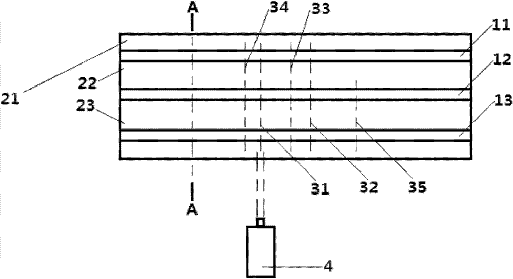
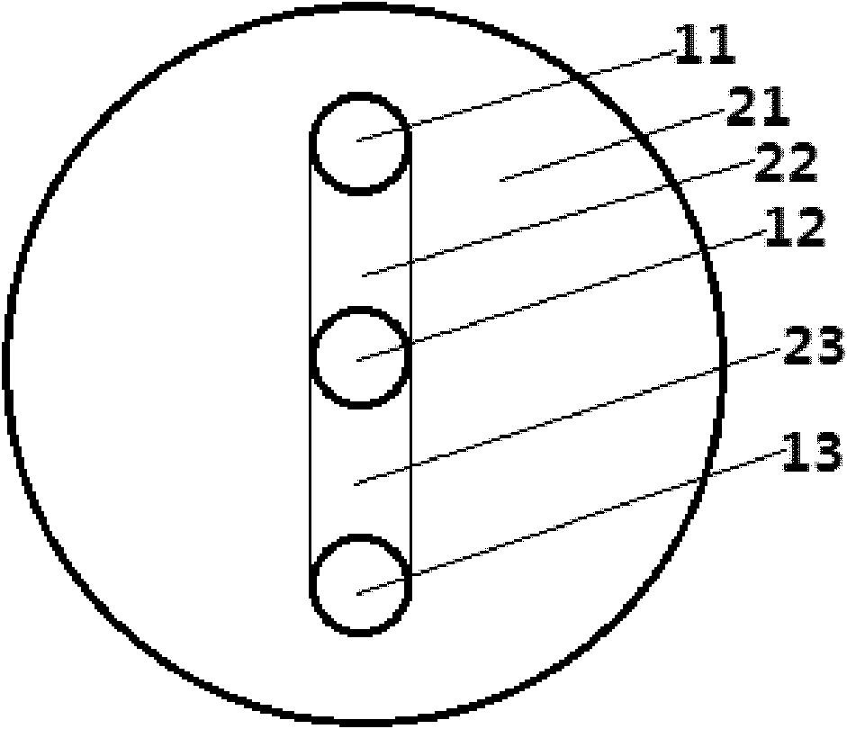
[0033] Step 1, take a three-core optical fiber whose length is 1 centimeter, including the first core 11, the second core 12 and the third core 13 whose refractive index is 1.461, the first core 11 and the second core The distance between the centers of the sub-12 and between the centers of the second core 12 and the third core 13 is 30 microns, and the centerlines of the first core 11, the second core 12 and the third core 13 are in a plane Inside, the materials of the first cladding inner 22 and the second cladding inner 23 of the optical fiber are doped with the same doping element Ge.
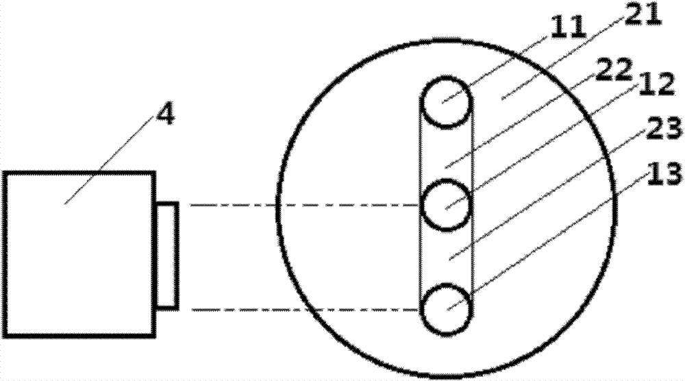
[0034] In step 2, an ultraviolet laser 4 is configured, and the ultraviolet laser adopts an ArF excimer laser.
[0035] Step 3: On the three-core optical fiber, choose any position as the first irradiation position 31 , and set it as the second irradiatio...
Embodiment 2
[0046] Embodiment 2, a manufacturing method of an all-fiber flat filter, the manufacturing method comprising the following steps:
[0047] Step 1, take a length of 5 cm, including a three-core optical fiber whose refractive index is 1.462 for the first core 11, the second core 12 and the third core 13, the first core 11 and the second core The distance between the centers of the sub-12 and between the centers of the second core 12 and the third core 13 is 20 microns, and the centerlines of the first core 11, the second core 12 and the third core 13 are in a plane Inside, the materials of the first cladding inner 22 and the second cladding inner 23 of the optical fiber are doped with the same doping elements Ge and B.
[0048] Step 2, configuring an ultraviolet laser 4, the ultraviolet laser adopts a KrF excimer laser.
[0049] Step 3: On the three-core optical fiber, choose any position as the first irradiation position 31 , and set a position 1000 microns away from the first...
Embodiment 3
[0060] The difference between embodiment three and embodiment one and two is:
[0061] Step 1, take a three-core optical fiber whose length is 3 centimeters, including the first core 11, the second core 12 and the third core 13 whose refractive index is 1.463, the first core 11 and the second core The distance between the centers of the sub-12 and between the centers of the second core 12 and the third core 13 is 25 microns, and the centerlines of the first core 11, the second core 12 and the third core 13 are in a plane Inside, the materials of the first cladding inner 22 and the second cladding inner 23 of the optical fiber are doped with the same doping element P.
[0062] Step 2, configure an ultraviolet laser 4, the ultraviolet laser uses CO 2 laser.
[0063] Step 3: On the three-core optical fiber, choose any position as the first irradiation position 31 , and set a position 300 microns away from the first irradiation position 31 as the second irradiation position 32 ....
PUM
 Abstract
Description
Claims
Application Information
 - Generate Ideas
- Intellectual Property
- Life Sciences
- Materials
- Tech Scout
- Unparalleled Data Quality
- Higher Quality Content
- 60% Fewer Hallucinations
Browse by: Latest US Patents, China's latest patents, Technical Efficacy Thesaurus, Application Domain, Technology Topic, Popular Technical Reports.
© 2025 PatSnap. All rights reserved.Legal|Privacy policy|Modern Slavery Act Transparency Statement|Sitemap|About US| Contact US: help@patsnap.com