
Overall test and construction method of differential protection system of large-scale transformer

A differential protection and whole group test technology, applied in the direction of instruments, measuring electrical variables, measuring devices, etc., can solve the problems of the test method that does not reflect the large current of the primary circuit, the limited capacity of the test equipment, etc., and achieve the goal of debugging technology Simplified equipment, guaranteed complete test significance, and easy operation

Active Publication Date: 2011-06-15
CHINA METALLURGICAL CONSTR ENG GRP
View PDF4 Cites 24 Cited by
  • Summary
  • Abstract
  • Description
  • Claims
  • Application Information

AI Technical Summary

Problems solved by technology

This test method has obvious limitations and defects for the whole set of tests on the differential protection system of large main transformers: first, it is necessary to obtain a large fault current of thousands of amps, the capacity of the test equipment is limited, and the capacity of the conventional large current generator Only 6KVA / 1000A; Secondly, the differential protection requires the protection range between the three-phase current transformers on the high-voltage side and low-voltage side of the main transformer, and the three-phase current transformers on the high-voltage and low-voltage sides must simultaneously output a certain phase and amplitude value of current
However, this method has the following disadvantages: First, it is limited to the operation test of the secondary circuit of the transformer, and does not reflect the test method for the large current of the primary circuit; it has considerable limitations for large-scale transformer systems, because the current is large, so reliable short circuit And convenient short circuit is an important feature to achieve good and fast

Method used


Image

  • Overall test and construction method of differential protection system of large-scale transformer
  • Overall test and construction method of differential protection system of large-scale transformer
  • Overall test and construction method of differential protection system of large-scale transformer

Examples


Embodiment Construction

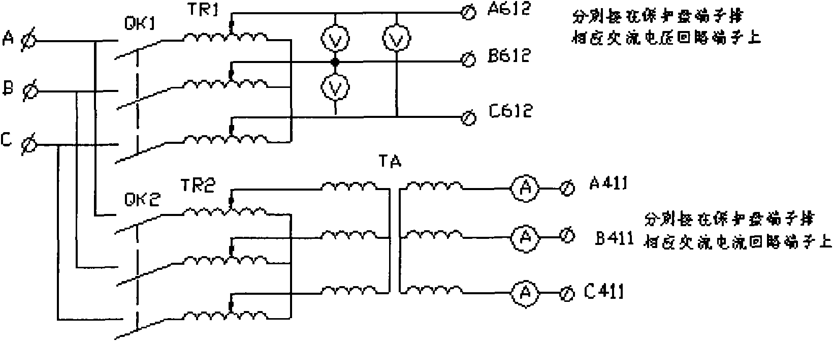
[0025] The present invention adopts a whole set of test methods, mainly short-circuiting the low-voltage side of the transformer and adding a low-voltage power supply to the high-voltage side, such as a 380V construction power supply, or short-circuiting the high-voltage side of the transformer and adding a power supply to the low-voltage side to obtain a short-circuit large current. So this whole set of tests is also called short-circuit test.

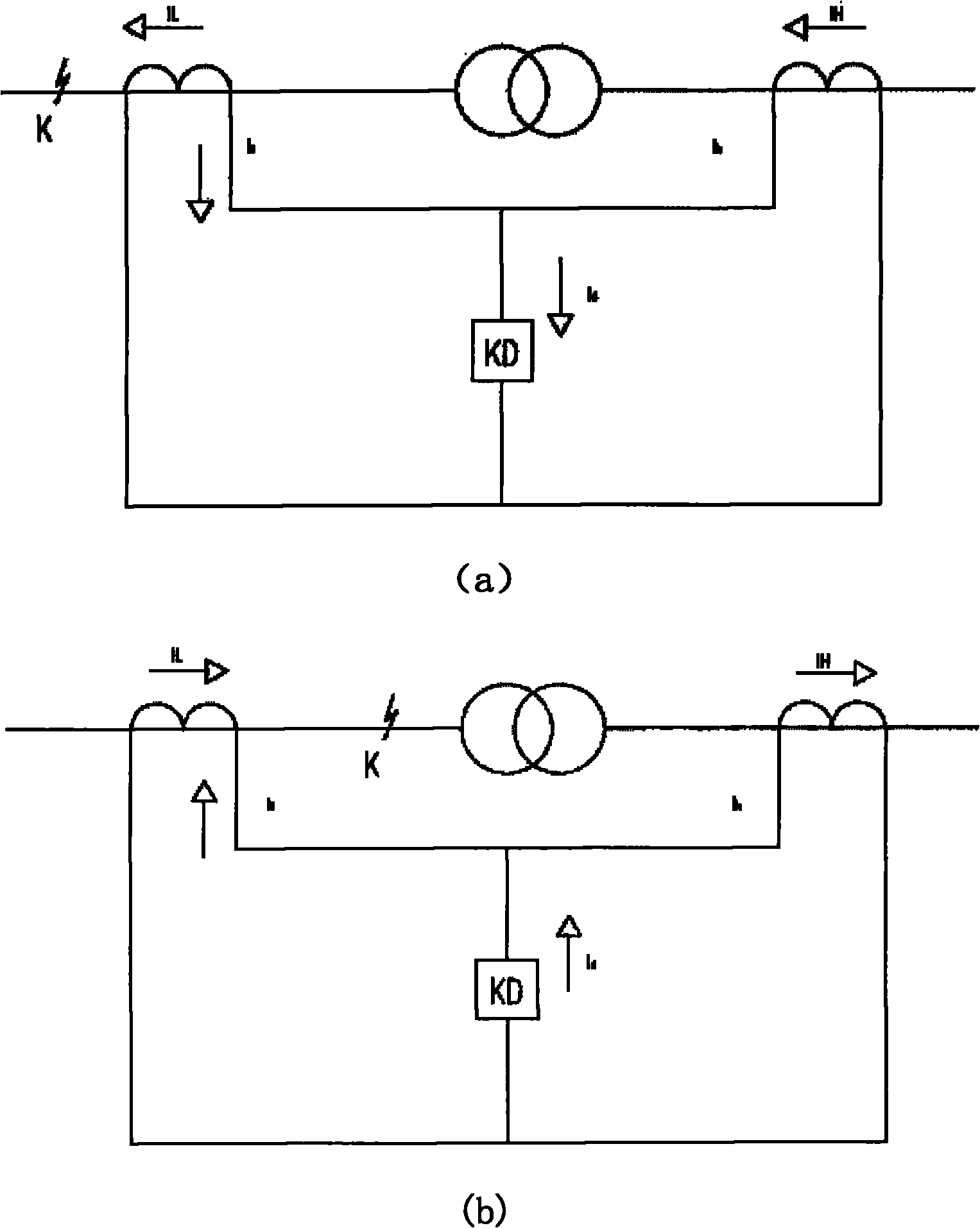
[0026] 1. The basic principle of transformer differential protection:

[0027] The differential protection system implements transformer power supply disconnection protection after comparing the current magnitude and phase of the high and low voltage sides of the transformer. When the transformer is in normal operation, the currents of the secondary circuits of the high and low voltage side current transformers are equal in size and opposite in direction, the current flowing through the differential circuit is zero, and the differenti...


PUM


Abstract

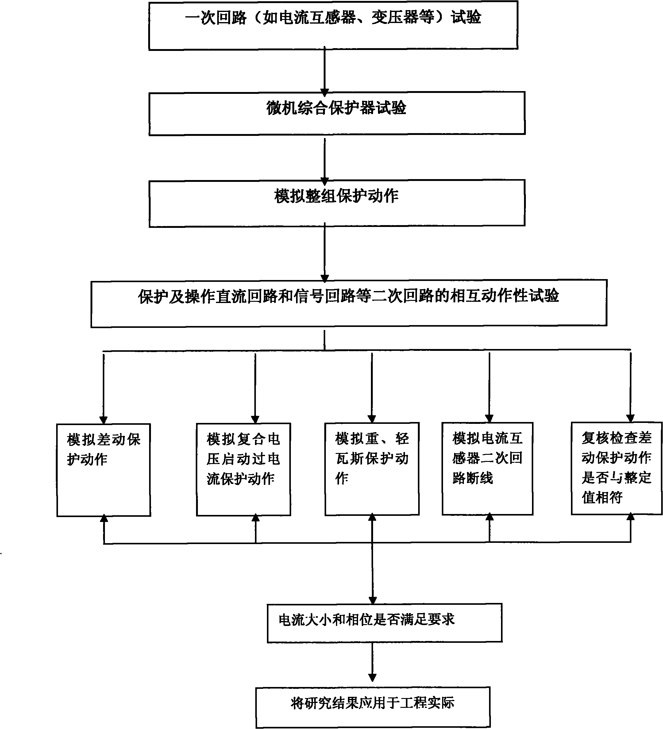
The invention discloses an overall test and construction method of a differential protection system of a large-scale transformer, which comprises the steps of: firstly, short-connecting an appropriate position at the low-voltage side of the transformer with a bus bar by using a short circuit clamp and utilizing the characteristic of short-circuit impedance of the transformer, and arranging a low-voltage power supply at the high-voltage side of the transformer so as to obtain short-circuit large current in a primary circuit of the differential protection system of the transformer; then, clamping the current of all phases in a differential current secondary circuit of a relay protecting screen by a double-pincerlike phase meter, recording the phase differences and values of all phases, and comparing with all phases of current of the differential circuit of a synthetic microcomputer protection device; and displaying the numerical value on the double-pincerlike phase meter, and outputtinga tripping signal when the numerical value reaches a certain operating value so as to realize the overall test of the whole differential protection system of the transformer. In the test method, lines do not need to be disassembled or assembled, and any primary circuit or secondary circuit is not changed; and the test method is characterized by simpleness, convenience and high efficiency.

Description

technical field [0001] The invention relates to a method of testing electrical protection systems for transformers. Background technique [0002] In the power system, the whole set of tests on the electrical protection system of large transformers is a key link in the installation and commissioning of large transformers. At present, the load test method usually used in the differential protection test of large transformers, that is, when the system is put into the system for the first time, the differential protection tripping function of the microcomputer protection device is withdrawn, and after the transformer is powered on, it is deactivated after it is fully charged (to avoid malfunction) , and then let the transformer take part of the load required for the test, measure the hexagonal diagram, and measure the unbalanced voltage or current of the differential current circuit at the same time. Use this to confirm that the wiring, polarity, and setting values ​​of the sec...

Claims


Application Information

Patent Timeline
IPC IPC(8): G01R31/00
Inventor 王玉刘川康凤军黄丽
Owner CHINA METALLURGICAL CONSTR ENG GRP
Learn More