Turbine vane for a gas turbine and casting core for the production of such

A technology for turbine blades and gas turbines, applied in the field of turbine blades for gas turbines and cores for manufacturing such turbine blades, can solve problems such as unusable cores, core ruptures, and enlarged openings.

Inactive Publication Date: 2011-06-08
SIEMENS AG
View PDF6 Cites 8 Cited by
  • Summary
  • Abstract
  • Description
  • Claims
  • Application Information

AI Technical Summary

Problems solved by technology

However, this treatment leads to cores for which the openings provided on the core trailing edge are so large that only thinner separators remain between them.
But when manipulating the core, the core breaks at precisely this point, making the core unusable subsequently

Method used


Image

  • Turbine vane for a gas turbine and casting core for the production of such
  • Turbine vane for a gas turbine and casting core for the production of such
  • Turbine vane for a gas turbine and casting core for the production of such

Examples


Embodiment Construction

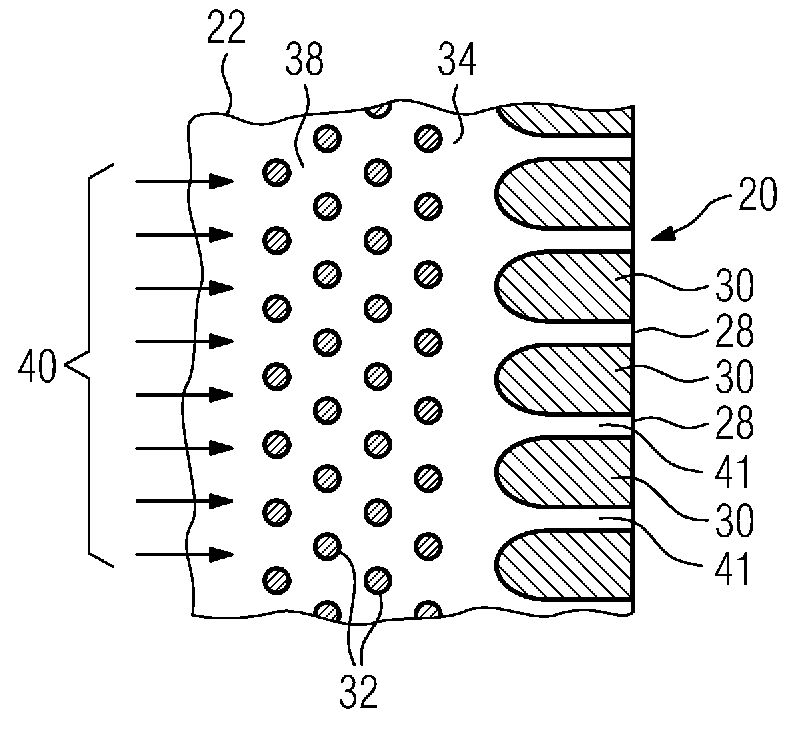
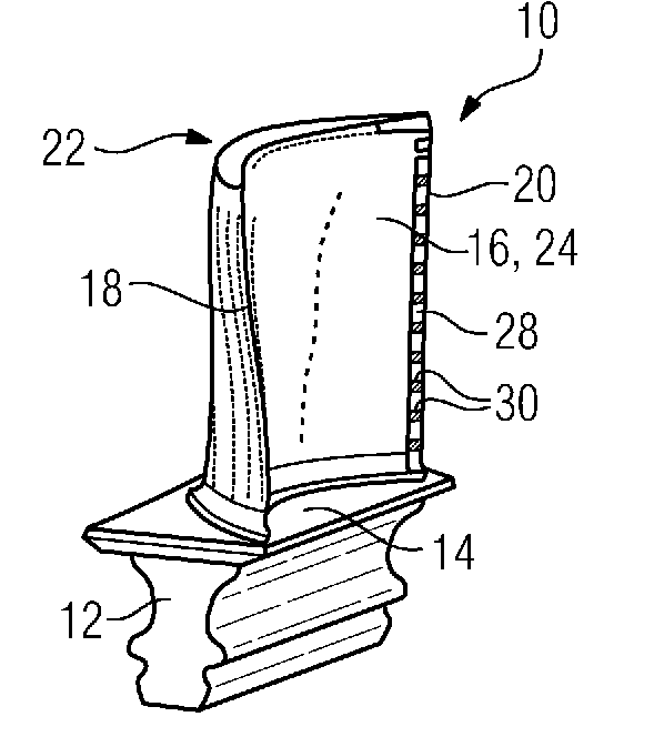
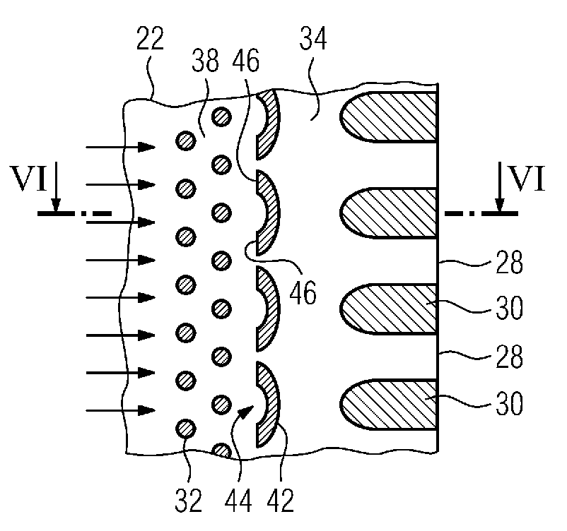
[0032] A gas turbine blade 10 relating to the invention is shown in perspective in FIG. 1 . The gas turbine blade 10 is designed as a rotor blade according to FIG. 1 . The invention can also be used in guide vanes (not shown) of gas turbines. The turbine blade 10 comprises a Christmas tree-shaped blade root 12 in cross section and a platform 14 arranged on the blade root. An aerodynamically curved blade airfoil 16 having a leading edge 18 and a trailing edge 20 is attached to the platform 14 . Cooling holes arranged as so-called “shower heads” are provided on the leading edge 18 , from which cooling holes flowing in the interior, preferably cooling air, can emerge. The blade airfoil 16 comprises a suction side wall 22 at the rear and a pressure side wall 24 at the front with respect to FIG. 1 . Along the trailing edge 20 are provided a plurality of trailing edge openings 28 which are separated from each other by separating webs 30 arranged therebetween. The trailing edge 2...


PUM


Abstract

The invention relates to a turbine vane having a novel interior structure. The invention further relates to novel turbulence elements (42) connected directly upstream of openings (28) disposed at the rear edge (20) of the vane blade (16) of the turbine vane. The same are disposed in a sequence, each having a flow side (44) against which a coolant (40) flows and which is at least partially arched in a concave manner according to the invention. Preferably, the turbulence elements (42) are configured in a crescent-shaped manner. This aerodynamically particularly unfavorable shape of the turbulence elements (42) causes increased pressure loss, thus complicating the through-flow of coolants. This makes it possible to enlarge the openings (28) without resulting in an increased consumption of coolant. The invention also provides a substantially more stable casting core (110), since the openings (130) required in the casting core (110) for the production of the webs (30) of a turbine vane may now be placed at further distances than before. This results in higher stability of the casting core (110) in the region of the casting core rear edge (120), thus the same is less prone to breakage in said region, and thus may be handled in a more robust manner.

Description

technical field [0001] The invention relates to a turbine blade for a gas turbine, having a hollow blade airfoil which can be circulated by hot gas, a plurality of openings distributed on the trailing edge of the blade airfoil for blowing out a coolant for cooling the turbine blade They are separated from one another by intervening partitions, wherein at least one cavity is provided in the interior of the blade airfoil, which is flow-connected to a plurality of the openings, in which cavity the A plurality of vortex elements are arranged upstream of the separator, each having an inflow side facing the coolant flow arriving there. Furthermore, the invention relates to a core for use in a casting device for producing a cast turbine blade according to the preamble of claim 1 , after the core has been removed from the cast turbine blade Cavities remain in the turbine blade through which coolant can flow. Background technique [0002] The aforementioned turbine blade and a core...

Claims


Application Information

Patent Timeline
Patent Type & Authority Applications(China)
IPC IPC(8): F01D5/18
CPCF05D2240/304F01D5/187F05D2260/22141F05B2250/712F05D2260/2212F05B2260/222F05D2240/122F05B2260/2241F05D2250/712
Inventor H-T.博尔姆斯F.艾哈迈德C.勒纳
Owner SIEMENS AG
Why Eureka
Try Eureka