
Micro electronmechanical element and micro electronmechanical spring element

A technology of micro-electromechanical components and spring components, applied in the field of micro-electromechanical components, can solve the problems of general products without suitable structure and inconvenience

Active Publication Date: 2011-06-08
PIXART IMAGING INC
View PDF6 Cites 2 Cited by
  • Summary
  • Abstract
  • Description
  • Claims
  • Application Information

AI Technical Summary

Problems solved by technology

[0005] This shows that the above-mentioned existing micro-electromechanical spring element obviously still has inconvenience and defects in structure and use, and needs to be further improved urgently.
In order to solve the above-mentioned problems, the relevant manufacturers have tried their best to find a solution, but for a long time no suitable design has been developed, and the general product has no suitable structure to solve the above-mentioned problems. This is obviously the relevant industry. Urgent problem

Method used


Image

  • Micro electronmechanical element and micro electronmechanical spring element
  • Micro electronmechanical element and micro electronmechanical spring element
  • Micro electronmechanical element and micro electronmechanical spring element

Examples


Embodiment Construction

[0063] In order to further explain the technical means and effects that the present invention takes to achieve the intended invention purpose, below in conjunction with the accompanying drawings and preferred embodiments, its specific implementation, structure, Features and their functions are described in detail below.

[0064] The following examples will illustrate the MEMS device of the present invention, but it is not intended to limit the type of the MEMS device of the present invention. Those skilled in the art will know that the MEMS element of the present invention can be any MEMS element that can move due to external force.

[0065] The aforementioned and other technical contents, features and effects of the present invention will be clearly presented in the following detailed description of preferred embodiments with reference to the drawings. For convenience of description, in the following embodiments, the same elements are denoted by the same numbers.

[0066] ...


PUM


Abstract

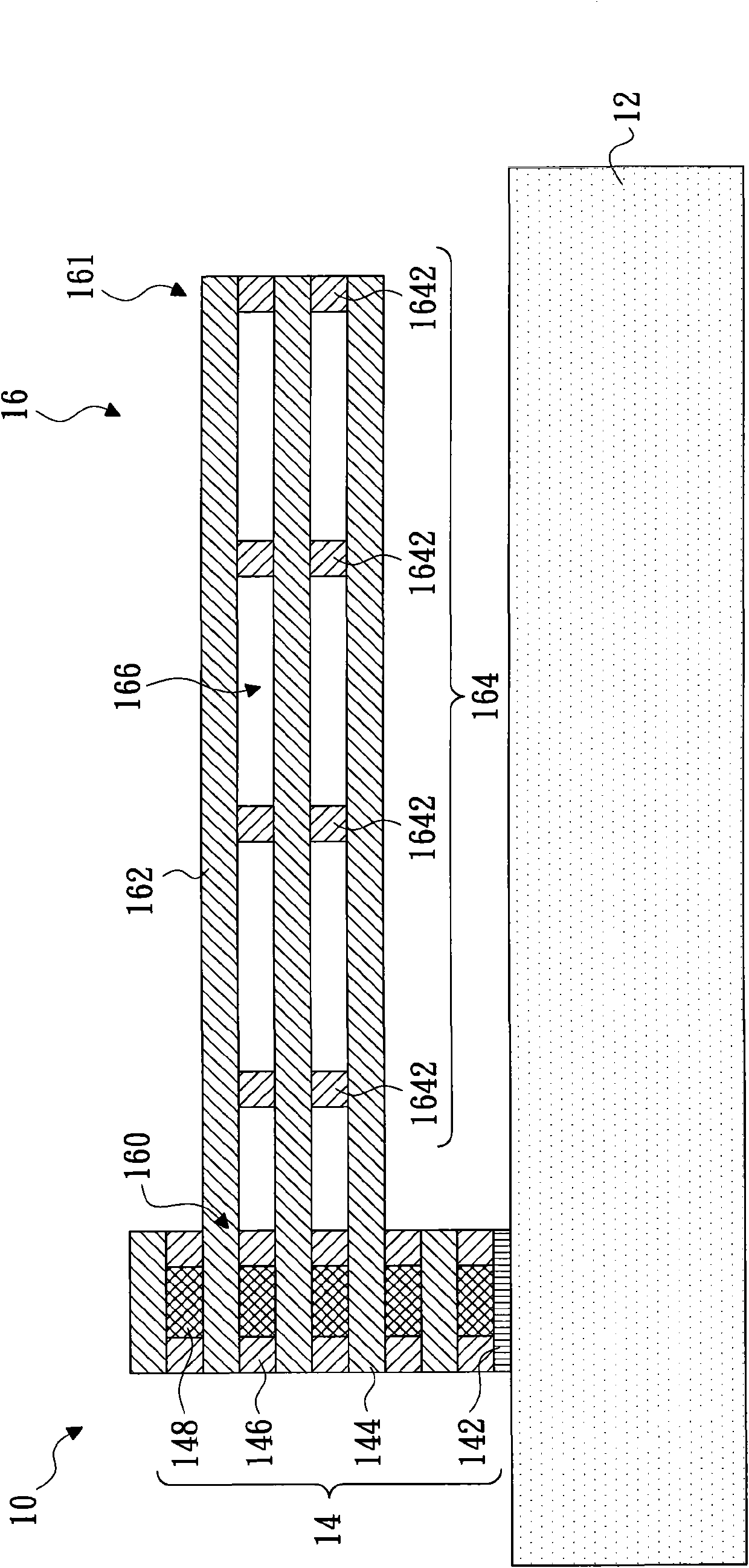
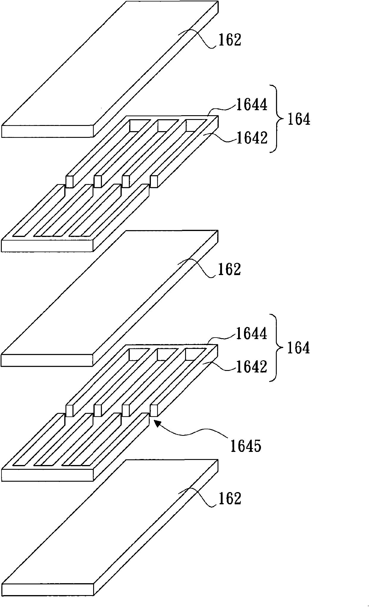
The invention relates to a micro electronmechanical element and a micro electronmechanical spring element. The micro electronmechanical element comprises a substrate, a fixed part and a movable part, wherein the fixed part is fixed on the substrate; the movable part is provided with a first end connected with the fixed part and a second end suspended above the substrate and comprises a plurality of metal layers and supporting layers connected between adjacent metal layers; and a hollow area is formed between each supporting layer and each connected metal layer. Because the micro electronmechanical spring element is in a hollow structure, the movable part can prevent bending and deforming caused by different thermal expansion coefficients of the metal layers and the film layers between the metal layers when the micro electronmechanical spring element is changed by the environment or the encapsulating temperature so that the micro electronmechanical spring element has favorable working performance.

Description

technical field [0001] The invention relates to a microelectromechanical element, in particular to a hollow microelectromechanical element and a microelectromechanical spring element. Background technique [0002] The development of Micro Electromechanical System (MEMS) technology has opened up a new technical field and industry, and its application fields are wide, for example, it is often used in MEMS inertial sensors such as accelerometers or gyroscopes. In these sensors, a MEMS spring element is usually required to connect and fix one end of the moving structure on the substrate, so that the moving structure can reciprocate in a certain direction. The conventional MEMS spring element is generally composed of silicon material or alternately stacked metal layers and oxide layers. [0003] However, since the thermal expansion coefficients of the metal layer and the oxide layer are different, the metal layer and the oxide layer will undergo different degrees of thermal expa...

Claims


Application Information

Patent Timeline
IPC IPC(8): B81B7/00B81B3/00
Inventor 王传蔚李昇达徐新惠
Owner PIXART IMAGING INC
Learn More