
Method and device for the pressure wave compensation of consecutive injections in an injection system of an internal combustion engine

A technology of injection system and internal combustion engine, which is applied in the direction of fuel injection control, internal combustion piston engine, combustion engine, etc., can solve the problem of insufficient tolerance of the second pre-injection amount in time, and achieve the effect of improving efficiency

Inactive Publication Date: 2011-06-01
ROBERT BOSCH GMBH
View PDF5 Cites 0 Cited by
  • Summary
  • Abstract
  • Description
  • Claims
  • Application Information

AI Technical Summary

Problems solved by technology

[0005] However, the quantity accuracy achievable with this prior art with respect to the temporal second pilot injection is not sufficient for future tolerance requirements deduced from future emission limit values.

Method used


Image

  • Method and device for the pressure wave compensation of consecutive injections in an injection system of an internal combustion engine
  • Method and device for the pressure wave compensation of consecutive injections in an injection system of an internal combustion engine
  • Method and device for the pressure wave compensation of consecutive injections in an injection system of an internal combustion engine

Examples


Embodiment Construction

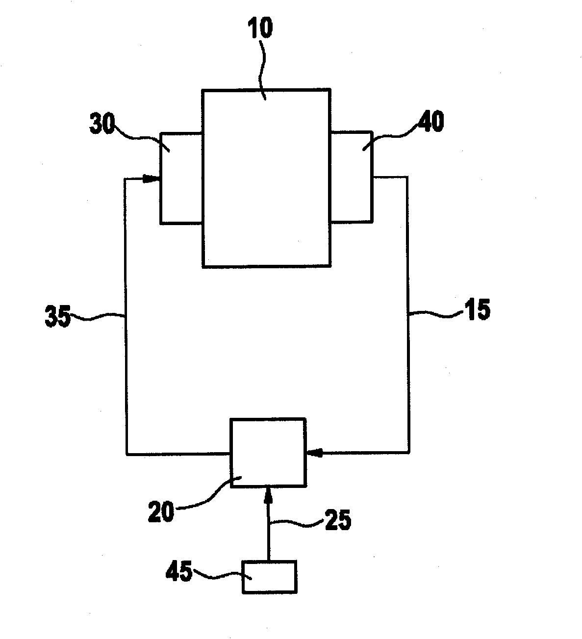
[0018] FIG. 1 shows a block diagram of the main elements of a fuel metering system of an internal combustion engine previously known from DE 199 45 618 A1. Internal combustion engine 10 receives a specific fuel quantity from fuel metering unit 30 at a specific time. Various sensors 40 detect measured values ​​15 characterizing the operating state of the internal combustion engine and transmit them to the control unit 20 . In addition, different output signals 25 of further sensors 45 are transmitted to the control device 20 . Detected measured value 15 characterizes a state of the fuel metering unit, such as the driver's desire. On the basis of these measured values ​​15 and further variables 25 , control device 20 calculates a trigger pulse 35 , which is applied to fuel metering unit 30 .

[0019] The internal combustion engine assumed here is preferably a direct-injection and / or self-ignition internal combustion engine. The fuel metering unit 30 can be designed in differe...


PUM


Abstract

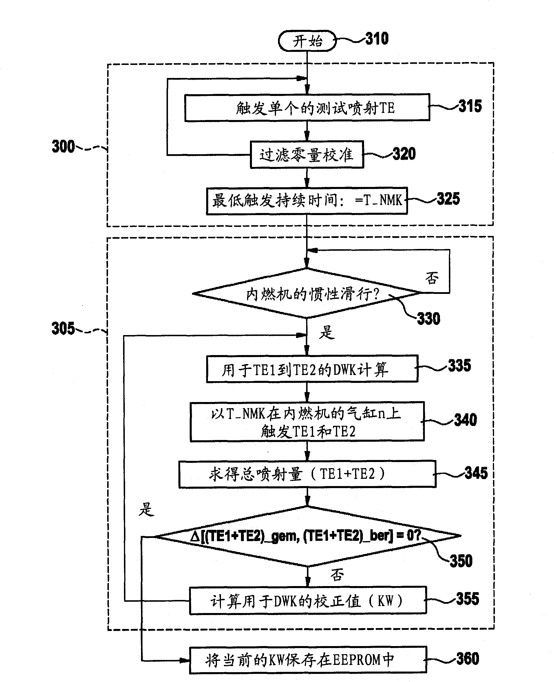
The present invention relates to a method and a device for controlling an injection system of an internal combustion engine, wherein at least two consecutive partial injections are compensated for by way of pressure wave compensation, it is provided in particular that two test injections having a predefined time lag between each other are controlled in a cylinder of the internal combustion engine, that the total amount injected of the at least two test injections is determined, and that a variance between the determined amount and an anticipated total amount injected is interpreted to be an error of the pressure wave compensation, and based thereon a corrective value for the pressure wave compensation is determined.

Description

technical field [0001] The present invention relates to a method and a device according to the preambles of the corresponding independent claims for controlling the injection of an internal combustion engine in a pressure-wave-compensated manner during partial injections which follow one another in time. system. Background technique [0002] For common rail diesel injection systems, the total injection quantity calculated from the driver's perspective is divided into several partial injection quantities on the basis of the torque requirement, for example, in the partial load range into two pre-injections and One main injection. The injection quantities of these partial injections should be as small as possible in order to minimize emission disadvantages. On the other hand, the pre-injection must be sufficiently large in order to continuously reduce the minimum quantities necessary for the engine, also taking into account all sources of tolerance. However, the known practi...

Claims


Application Information

Patent Timeline
Patent Type & Authority Applications(China)
IPC IPC(8): F02D41/40F02D41/24F02D41/38
CPCF02D41/2432F02D41/402F02D2250/04F02D41/2467Y02T10/44F02D43/02F02D41/3809F02D41/247Y02T10/40
Inventor M·瓦尔特Z·帕普茨特J·帕尔默S·博林格尔
Owner ROBERT BOSCH GMBH
Learn More