Advanced electro-active optic device

A technology of electroactive layer and equipment, which is applied in the direction of nonlinear optics, optics, optical components, etc., and can solve problems such as visual hazards

Inactive Publication Date: 2011-06-01
PIXELOPTICS
View PDF3 Cites 43 Cited by
  • Summary
  • Abstract
  • Description
  • Claims
  • Application Information

AI Technical Summary

Problems solved by technology

[0014] These disadvantages or hazards to human vision may be difficult to solve, especially (by way of example only) when driving at night, driving in the rain or working on a computer

Method used


Image

  • Advanced electro-active optic device
  • Advanced electro-active optic device
  • Advanced electro-active optic device

Examples


Embodiment Construction

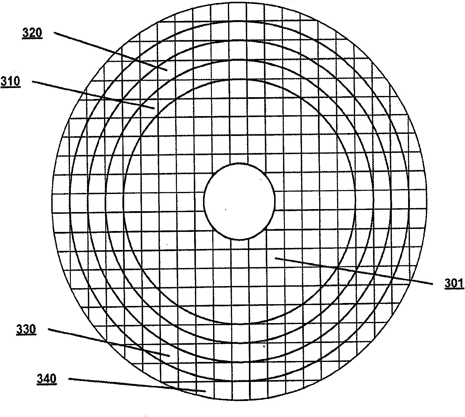
[0048] As used herein, an electro-active element refers to a device having optical properties that can be changed in response to the application of electrical energy. The variable optical property can be, for example, optical power, focal length, diffraction efficiency, depth of field, light transmission, tinting, opacity, refractive index, dispersion, or combinations thereof. The electroactive element may consist of two substrates and an electroactive material arranged between said two substrates. The substrate may be shaped and dimensioned to ensure that the electroactive material is contained within the substrate and cannot leak out. One or more electrodes may be disposed on each surface of the substrate that is in contact with the electroactive material. The electro-active element may include a power source operatively connected to the controller. The controller may be operably connected to the electrodes via electrical connections to apply one or more voltages to each e...


PUM


Abstract

Optical devices having a dynamic aperture and / or an apodization mask are provided. The aperture and / or mask may be provided by one or more electro-active elements, and may be used in an ophthalmic device that that is spaced apart from but in optical communication with an intraocular lens, a corneal inlay, a corneal onlay, or a spectacle lens that provide an optical power.

Description

[0001] Cross References to Related Applications [0002] This application claims the benefit of U.S. Application Serial No. 61 / 037,351, filed March 18, 2008, and U.S. Application Serial No. 61 / 060,291, filed June 10, 2008, which Each of is incorporated herein by reference in its entirety. technical field [0003] The present invention relates to intraocular lenses, intraocular lenses, corneal inlays and corneal onlays. More specifically, the present invention relates to intraocular lenses, intraocular lenses, corneal inlays and corneal onlays with apodization masks and / or dynamic apertures for increasing depth of field. The mask and / or aperture may be used in conjunction with at least partially correcting conventional errors (lower order aberrations, such as nearsightedness, hyperopia, regular astigmatism, and presbyopia) and / or non-routine errors (such as higher order aberrations) of the user's eyes Lenses for optical communication or integration. Background technique ...

Claims


Application Information

Patent Timeline
Patent Type & Authority Applications(China)
IPC IPC(8): A61F2/14A61F2/16G02C7/04G02F1/133
CPCG02C7/101G02C7/083A61F2/16G02C7/08A61F2/14A61F2/1627A61F2/15A61F2/1613G02F1/294
Inventor R·D·布卢姆J·N·哈多克W·科科纳斯基A·古普塔
Owner PIXELOPTICS
Why Eureka
Try Eureka