Optical network testing method, deice and system
一种测试方法、测试装置的技术,应用在光网络领域,能够解决中断业务、ONU掉线等问题,达到提高客户满意度的效果
- Summary
- Abstract
- Description
- Claims
- Application Information
AI Technical Summary
Problems solved by technology
Method used
Image

Examples
Embodiment 1
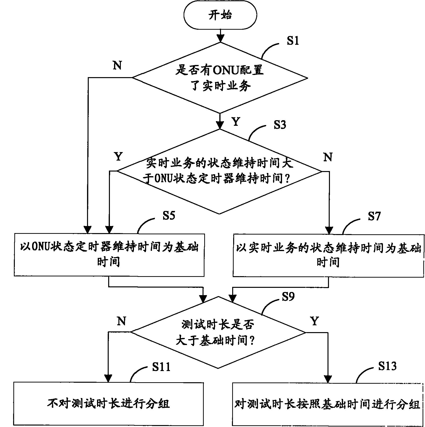
[0147] An embodiment of the present invention provides an optical network test method, which is applied to an integrated optical time domain reflectometer or an optical frequency domain reflectometer, including but not limited to an optical time domain reflectometer integrated in an optical central office device (such as: OLT) or in the case of optical frequency domain reflectometers; Figure 9 As shown, the optical network testing method specifically includes:
[0148] Step 901, obtain the longest test time of single group test, the longest test time of single group test described in this embodiment refers to: if the continuous test time of a group of tests is within the longest test time, optical terminal equipment (such as: ONU , ONT) will not return to the initial state, if the continuous test time of a group of tests exceeds the maximum test time, it will cause the optical terminal equipment to return to the initial state.
[0149] Step 902, when the total test time is g...
Embodiment 2
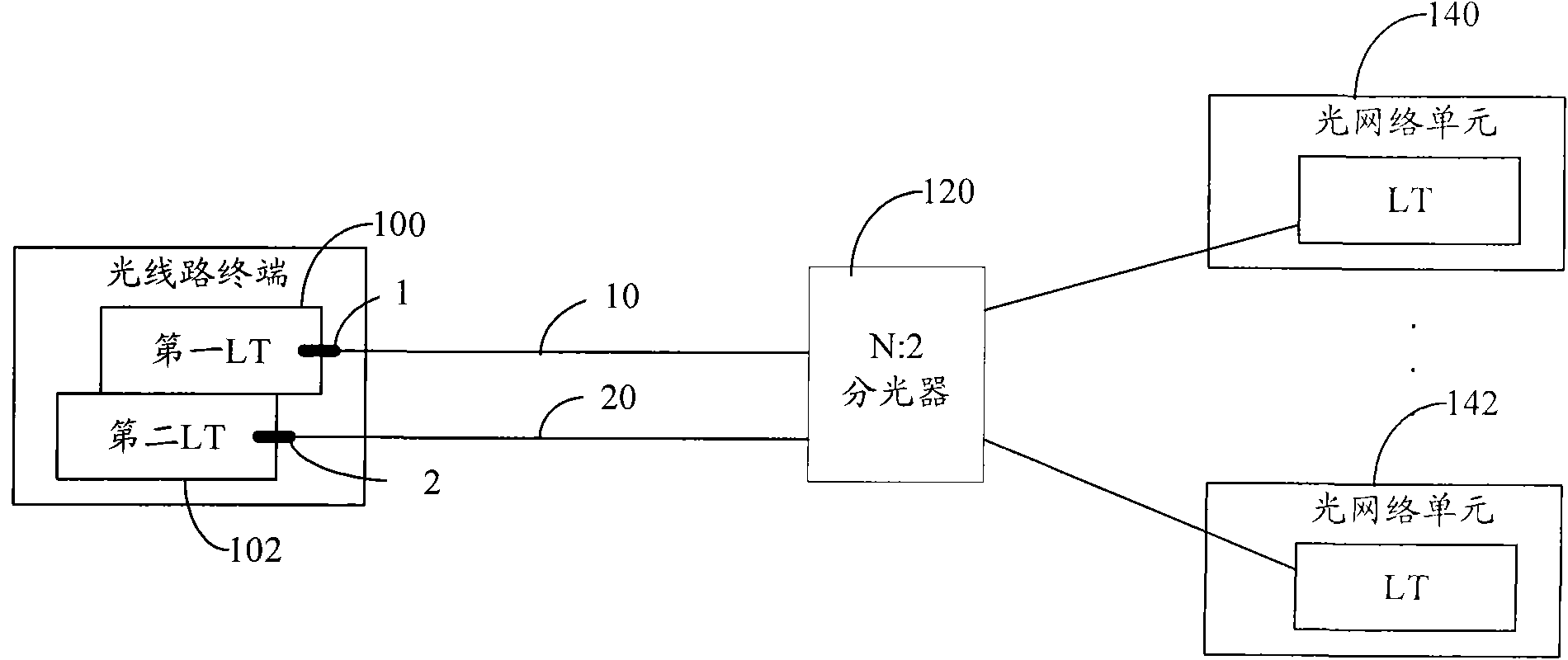
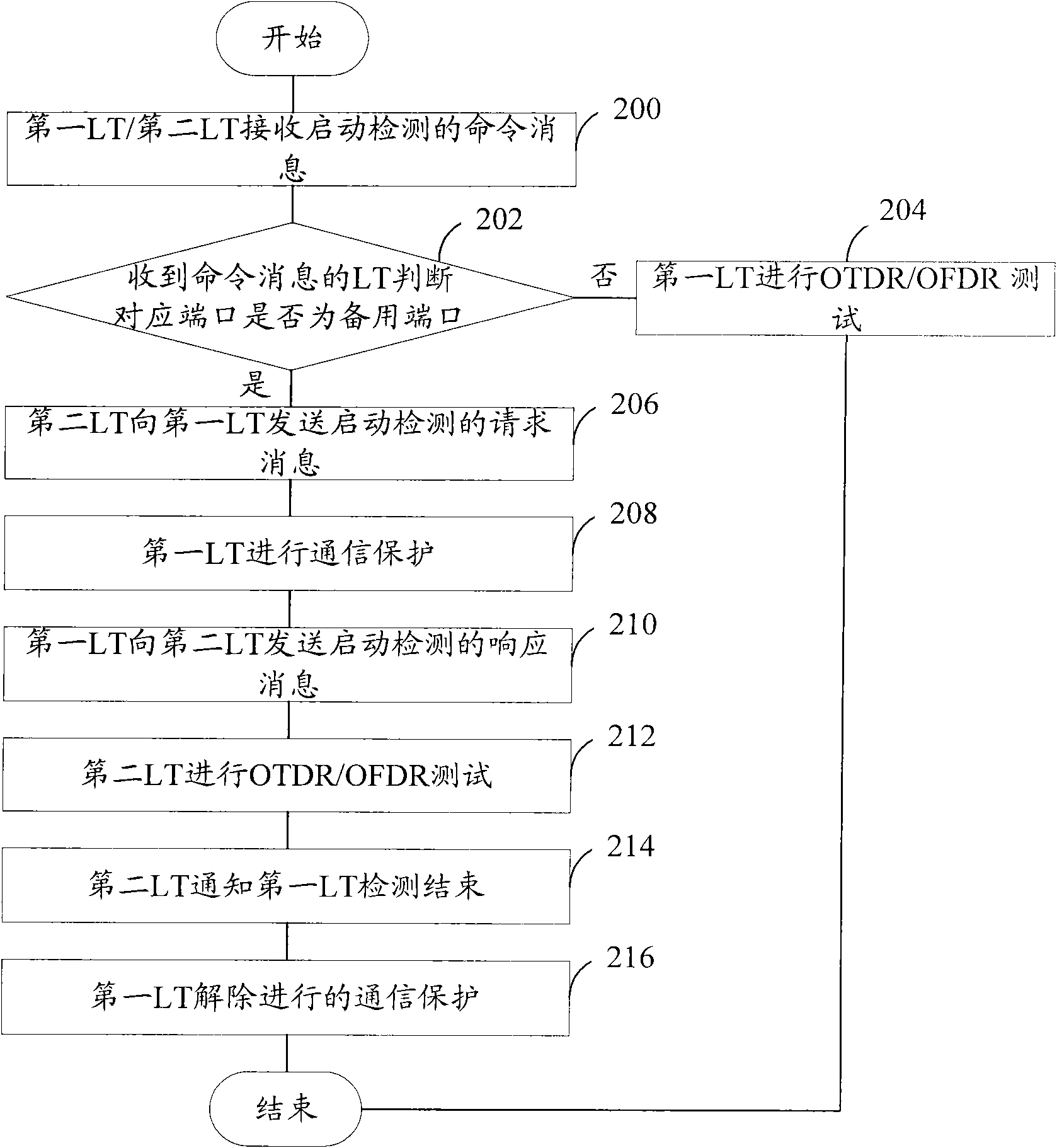
[0157] In this embodiment, an example of integrating an OTDR or an OFDR in an OLT and providing a user-side interface for a user through an ONU is used to describe an optical network testing method for integrating an OTDR or an OFDR provided by an embodiment of the present invention. Such as Figure 11 As shown, the method specifically includes:
[0158] Step B01, the OLT receives a command message to start passive optical network monitoring.
[0159] The command message can be sent to the OLT by the network management system through the SNMP protocol, can also be input by the maintenance personnel through the command line on the OLT, or can be triggered by an internal timer of the OLT.
[0160] The command message may include port information of the port to be monitored, test type, total test time, test pulse width, range and the like. The information of the test port may include the frame number, slot number, port number, etc. of the port, and the test type may be a period...
Embodiment 3
[0196] The embodiment of the present invention also provides an optical network testing device, which is applied to an integrated optical time domain reflectometer or an integrated optical frequency domain reflectometer, including but not limited to being applied to an integrated optical time domain In the case of reflectometers or optical frequency domain reflectometers; if Figure 12 As shown, the optical network testing device includes: a monitoring unit 51 , an acquiring unit 52 , a grouping unit 53 , a testing unit 54 , an indicating unit 55 , and a processing unit 56 .
[0197]Among them, the monitoring unit 51 is used to monitor the signal loss alarm / frame loss alarm of the port to be tested before obtaining the longest test time of the single group test. If a LOS or LOF alarm is detected, it means that all ONUs under the port to be tested have been disconnected. , without considering the problem of preventing the ONU from returning to the initial state during the test,...
PUM
 Abstract
Description
Claims
Application Information
 - R&D
- Intellectual Property
- Life Sciences
- Materials
- Tech Scout
- Unparalleled Data Quality
- Higher Quality Content
- 60% Fewer Hallucinations
Browse by: Latest US Patents, China's latest patents, Technical Efficacy Thesaurus, Application Domain, Technology Topic, Popular Technical Reports.
© 2025 PatSnap. All rights reserved.Legal|Privacy policy|Modern Slavery Act Transparency Statement|Sitemap|About US| Contact US: help@patsnap.com