
Method for producing rotor

A manufacturing method and rotor technology, which are used in rotary piston/swing piston pump components, rotary piston pumps, rotary piston machines, etc. Defect and high problems, to achieve the effect of high production efficiency

Inactive Publication Date: 2014-11-26
SHOWA DENKO KK
View PDF8 Cites 0 Cited by
  • Summary
  • Abstract
  • Description
  • Claims
  • Application Information

AI Technical Summary

Problems solved by technology

[0007] In the conventional method of manufacturing a rotor disclosed in Patent Document 1 above, the excess portion of the rotor material obtained by forging is cut off by cutting. Low
Therefore, as long as the production efficiency is low, it is very difficult to improve the overall production efficiency.
[0008] In addition, in the conventional rotor manufacturing method described in the above-mentioned Patent Document 2, the remaining material part closing the lower end of the vane groove is punched and removed by using a punch with a groove. Generally, it is difficult to accurately control the fracture position in the punching process. And there is a high possibility of undesired cracks or chipping, making it impossible to properly remove the remainder

Method used


Image

  • Method for producing rotor
  • Method for producing rotor
  • Method for producing rotor

Examples


no. 2 approach

[0188] Figures 21 to 26 The figure which shows the rotor material (1) obtained by the forging process of 2nd Embodiment of this invention. As shown in the above figure, in the second embodiment, the rotor blank (1) is composed of the rotor part (2) and the rest parts (5), (6), and the rotor part (2) does not include the rest part (5). ), (6).

[0189] The remaining material parts (5), (6) are provided so as to protrude from the one end surface (2a) of the rotor part (2) to the one end side.

[0190] In addition, in the rotor blank (1) of this embodiment, the one end surface (3a) of the central hole (3) does not reach the inside of the remaining material part (5), and the one end surface (3a) is arranged at a lower position than the one end surface (3a) of the rotor part (2). 2a) More medial.

[0191] In addition, the one end surface (4a) of the vane groove (4) also does not reach the inside of the residual material part (6), and the one end surface (4a) is arranged on the ...

Embodiment 1

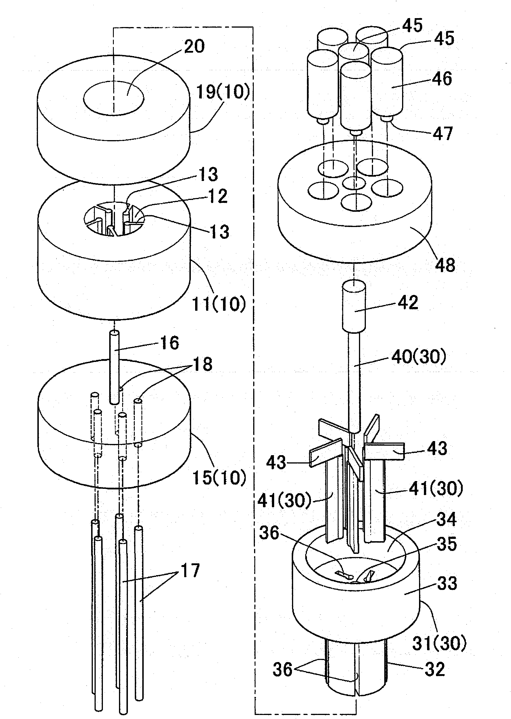
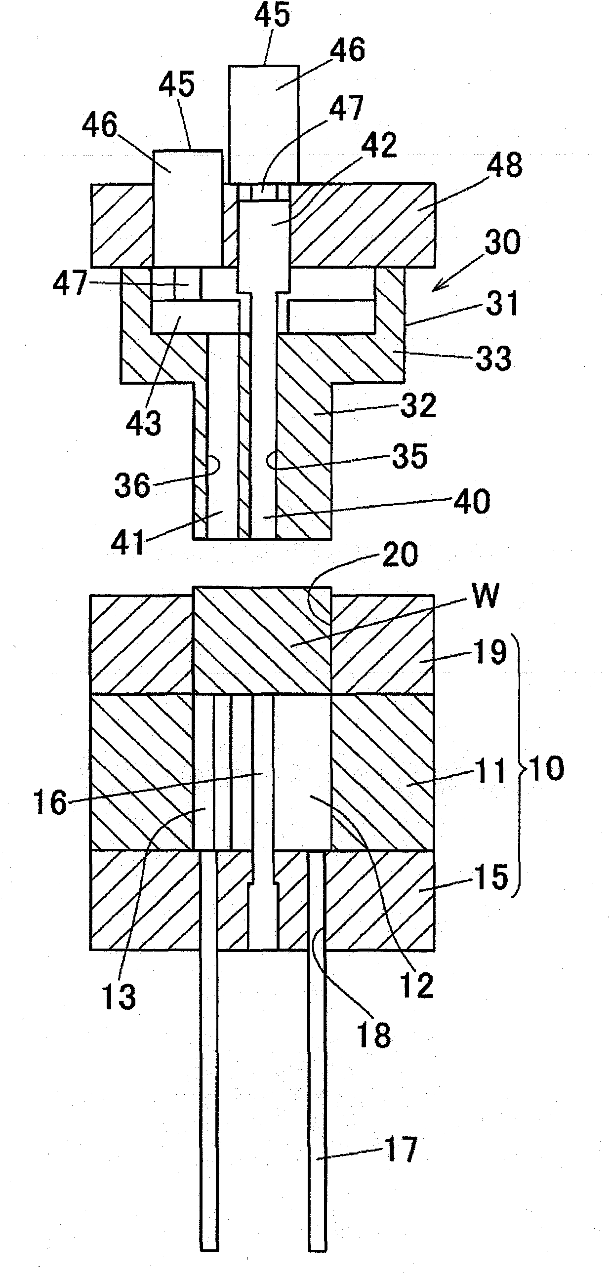
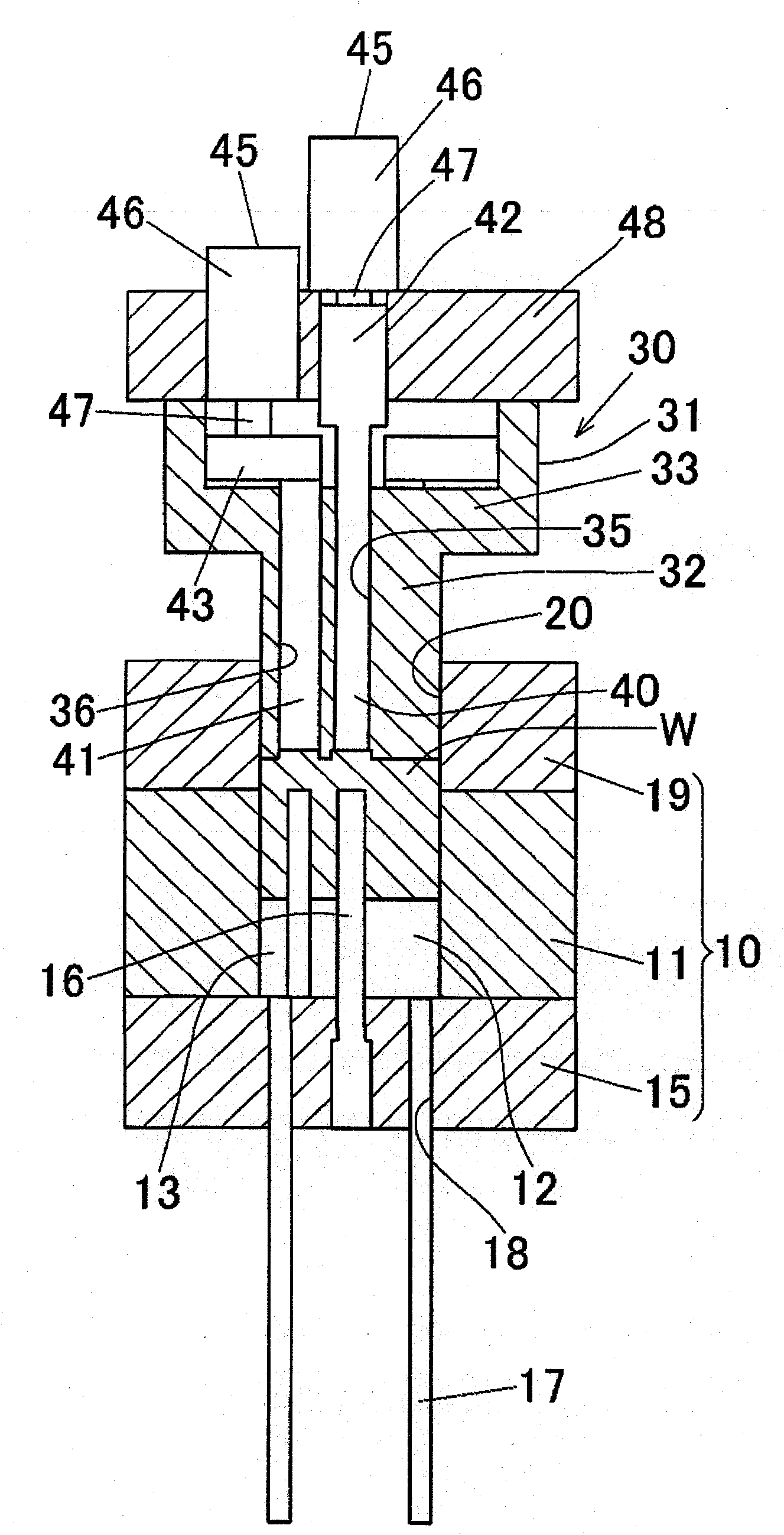
[0219] use figure 1 Forged with the forging die (10), (30) shown in Fig. 2 image 3 Indicated rotor blank (1). The above-mentioned rotor blank (1) is used to manufacture Figure 4 The material of the aluminum alloy rotor (R) shown.

[0220] In the above rotor (R), the outer diameter is 52mm, the height is 50mm, the diameter of the center hole (3) is 10mm, the number of blade grooves (4) is 5, the groove width is 3mm, the groove depth is 15mm, the offset dimension (U) is 10mm. In addition, A390 was used as the material alloy.

[0221] In addition, as shown in the following Table 1, in the above-mentioned forging die, the gap (D5) between the center pin (16) of the lower die (10) and the circular hole (35) of the upper die (30) is set to 0.1mm, The gap ( D6 ) between the blade portion ( 13 ) of the lower mold ( 10 ) and the flat hole ( 36 ) of the upper mold ( 30 ) was also set to 0.1 mm in the same manner as above.

[0222] In addition, the distance (breaking length D3) b...

Embodiment 2

[0232] As shown in Table 1, except that the breaking lengths (D3) and (D4) of the remaining parts (5) and (6) were set to "0", the rotor (R) was produced in the same manner as in Example 1 above. .


PUM

PropertyMeasurementUnit
thicknessaaaaaaaaaa
porosityaaaaaaaaaa
thicknessaaaaaaaaaa

Abstract

A rotor is produced efficiently. The present invention is directed to a rotor producing method. The present invention includes a forging step for obtaining a rotor material 1 having a cylindrical columnar rotor portion 2 in which a plurality of vane grooves 4 extending along an axial direction are formed in an outer peripheral portion at intervals in a circumferential direction and an excess thickness portion 6 integrally formed on one end face of the rotor portion 2 so as to protrude toward one end side of the rotor portion 2 and close the one end side of the vane groove 4, and an excess thickness portion removing step for obtaining a rotor R having the vane groove 4 opened at the one end side by hitting the excess thickness portion 6 with an impact applying member to thereby remove the excess thickness portion 6 from the rotor portion 2.

Description

technical field [0001] The present invention relates to a rotor manufacturing method for manufacturing a rotor having vane (bein, impeller) grooves on its outer periphery and related technologies. Background technique [0002] A rotor of a compressor or a rotor of a rotary vacuum pump for brake control generally has a plurality of vane grooves parallel to the axis formed at equal intervals in the circumferential direction on the outer peripheral portion. In addition, rotors of rotary compressors for air conditioners installed in automobiles or rotors of rotary vacuum pumps for brake control are generally made of aluminum alloy for the purpose of weight reduction, and are manufactured by forging. [0003] For example, in the rotor manufacturing method described in the following patent document 1, a blade portion for forming a blade groove is formed in a forming hole of a lower die (lower die), and the blade portion placed on the forming hole is placed on the forming hole by a...

Claims


Application Information

Patent Timeline
Patent Type & Authority Patents(China)
IPC IPC(8): F04C18/344F04C29/00
CPCB21J5/00B21J5/02F04C2240/20F01C21/08B21K3/00F04C2230/25F04C2230/10F04C2/344B21J5/12F04C18/344F04C29/00
Inventor 山田英实远藤大辅
Owner SHOWA DENKO KK
Learn More