
Liquid level detection balance device used for hemodialysis

A technology for hemodialysis and liquid level detection, which is applied in dialysis systems, buoy liquid level indicators, suction devices, etc., can solve the problems of large fluctuations in pressure sensor signals, high requirements for processing accuracy of double pumps, and high cost of double pumps. Achieve the effect of simple manufacturing process and control, low manufacturing cost and simple control

Active Publication Date: 2011-05-25
SWS HEMODIALYSIS CARE CO LTD
View PDF5 Cites 12 Cited by
  • Summary
  • Abstract
  • Description
  • Claims
  • Application Information

AI Technical Summary

Problems solved by technology

[0004] 2. The pressure control method is used to achieve the balance of dialysate and waste liquid, the signal of the pressure sensor fluctuates greatly, and the accuracy is not high
[0005] 3. The balance of liquid and waste liquid is achieved by using the double pump method, which requires high processing precision for the double pump and the cost of the double pump is relatively high

Method used


Image

  • Liquid level detection balance device used for hemodialysis
  • Liquid level detection balance device used for hemodialysis
  • Liquid level detection balance device used for hemodialysis

Examples


Embodiment 1

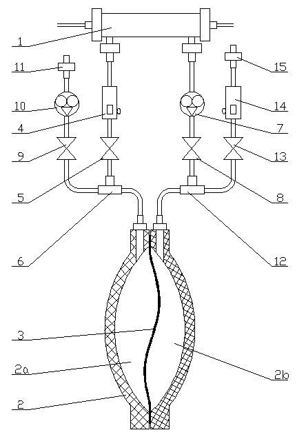
[0026] Such as figure 1 As shown, a balancer 2 is provided outside the hemodialyzer 1. The balancer 2 is composed of two symmetrical cavity hooks, and the two cavities are fixed by bolts. A diaphragm 3 is arranged in the balancer 2, the edge of the diaphragm 3 is pressed by the cavity of the balancer 2, and the diaphragm 3 separates the inner chamber of the balancer 2 into a first chamber 2a and a second chamber 2b. The outer membrane joint at one end of the hemodialyzer 1 is connected to the liquid outlet of the first liquid level detector 4 through a pipeline, and the liquid inlet of the first liquid level detector 4 is connected to the outlet of the second electromagnetic valve 5 through the pipeline. The liquid inlet of the second electromagnetic valve 5 is connected with the first end of the first three-way joint 6 through the pipeline; the outer membrane joint at the other end of the hemodialyzer 1 is connected with the inlet of the second hydraulic pump 7 through the p...

Embodiment 2

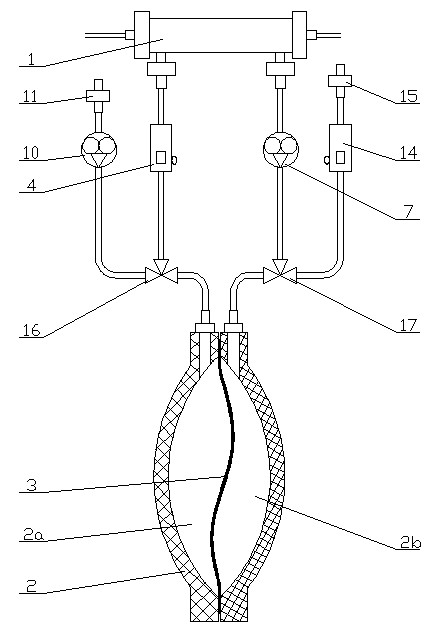
[0035] Such as figure 2 As shown, the outer membrane joint at one end of the hemodialyzer 1 is connected to the liquid outlet of the first liquid level detector 4 through the pipeline, and the liquid inlet of the first liquid level detector 4 is connected to the first three-way solenoid valve through the pipeline. 16 is connected to the liquid outlet; the outer membrane joint at the other end of the hemodialyzer 1 is connected to the liquid inlet of the second hydraulic pump 7 through the pipeline, and the liquid outlet of the second hydraulic pump 7 is connected to the second three-way electromagnetic through the pipeline. The inlet end of valve 17 is connected. The common end of the first three-way solenoid valve 16 communicates with the first chamber 2a of the balancer 2 through a pipeline, and the liquid inlet end of the first three-way solenoid valve 16 communicates with the liquid outlet of the first hydraulic pump 10 through a pipeline. The liquid inlet of the first h...


PUM


Abstract

The invention discloses a liquid level detection balance device used for hemodialysis, which is characterized in that the membrane external joint of one end of a hemodialyzer is sequentially connected with a first liquid level detector and a second solenoid valve in series and then is connected with the first end of a first T-joint, and the membrane external joint of the other end of the hemodialyzer is sequentially connected with a second hydraulic pump and a third solenoid valve in series and then is connected with the first end of a second T-joint; the second end of the first T-joint is communicated with a first chamber of a balancer, the third end of the first T-joint is sequentially connected with a first solenoid valve and a first hydraulic pump in series, and then is connected with a dialysate joint; and the second end of the second T-joint is communicated with the second chamber of the balancer, and the third end of the second T-joint is sequentially connected with a forth solenoid valve and a second liquid level detector in series and then is connected with a waste liquid joint. In the invention, the balancer is adopted as the volume balance device, the control is simple, and the manufacturing cost is lower; and whether the membrane in the balancer is pushed into the position or not is monitored by a liquid level detection method, both the manufacturing process and control are simpler, and the precision is ensured.

Description

technical field [0001] The invention belongs to the technical field of blood purification, and in particular relates to a liquid level detection and balance device for hemodialysis. Background technique [0002] At present, dialysis equipment in blood purification generally adopts flow meter, pressure control method or double pump method to control the balance of dialysate and waste liquid. The existing shortcomings are: [0003] 1. The flow meter is used to control the balance of dialysate and waste liquid, which requires high accuracy of the flow meter, and the manufacturing of the flow meter is complicated, and self-calibration needs to be continuously performed midway. [0004] 2. The pressure control method is adopted to realize the balance of dialysate and waste liquid, and the signal of the pressure sensor fluctuates greatly, and the precision is not high. [0005] 3. The balance of liquid and waste liquid is realized by using the double pump method, which requires h...

Claims


Application Information

Patent Timeline
IPC IPC(8): A61M1/16G01F23/30
CPCA61M2001/1635A61M1/16A61M1/1635
Inventor 高光勇吴雄飞任应祥童锦
Owner SWS HEMODIALYSIS CARE CO LTD
Learn More