Adjustable gain low noise amplifier

A low-gain technology for amplifiers, applied in the direction of high-frequency amplifiers, amplification control, and control of components of amplification devices, can solve problems such as the inability to directly realize the logarithmic linear relationship between gain and gain control voltage

Inactive Publication Date: 2011-05-18
HANGZHOU SILAN MICROELECTRONICS
View PDF0 Cites 21 Cited by
  • Summary
  • Abstract
  • Description
  • Claims
  • Application Information

AI Technical Summary

Problems solved by technology

The continuous time adjustable gain low noise amplifier (LNA) can be realized by adjusting the load size, increasing the pre / post attenuator, or adjusting the operating current. The variable load is generally composed of MOS resistors in the linear region, and the continuous time Most attenuators are based on MOS resistors, which are the same as the method of adjusting the working current. Since the I-V characteristics of MOS tubes satisfy the square rate relationship, the logarithmic linear relationship between gain and gain control voltage cannot be directly realized.

Method used


Image

  • Adjustable gain low noise amplifier
  • Adjustable gain low noise amplifier
  • Adjustable gain low noise amplifier

Examples


Embodiment Construction

[0044] The content of the present invention will be further described below in conjunction with the accompanying drawings.

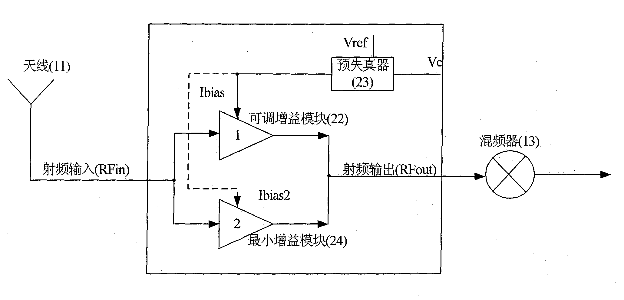
[0045] adjustable-gain low-noise amplifiers, such as figure 2 As shown, including an adjustable gain block (22), a predistorter (23) and a minimum gain block (24):

[0046] The radio frequency is input to the adjustable gain module (22) and the minimum gain module (24);

[0047] After the predistorter (23) compares the gain control voltage Vc with the reference voltage Vref, it is converted into a first bias current Ibias, and the first bias current Ibias is provided to the adjustable gain module (22);

[0048] The minimum gain module (24) provides minimum gain control, and the minimum gain module (24) inputs the second bias current Ibias2 to adjust its gain;

[0049] The output of the adjustable gain module (22) and the output of the minimum gain module (24) are combined as the radio frequency output of the adjustable gain low noise amplifier.

[00...


PUM


Abstract

The invention provides an adjustable gain low noise amplifier, wherein a predistorter compares gain control voltage Vc with reference voltage Vref, converts into first bias current Ibias, and the first bias current Ibias is supplied for an adjustable gain module; a minimum gain module provides minimum gain control and inputs second bias current Ibias2 for adjusting the gain; and the output of theadjustable gain module and the output of the minimum gain module are combined as the radio-frequency output of the adjustable gain low noise amplifier. Because the gain of the adjustable gain module is controlled by a bias signal after predistortion, the gain of the adjustable low noise amplifier near the reference voltage and the gain control voltage are in logarithm linear relation, and simultaneously the maximum gain and the minimum gain of the adjustable gain low noise amplifier are accurately controlled by arranging the minimum gain module. The adoption of bias current for controlling the gain has the advantage that when the signal is larger, the working current of the amplifier is greatly reduced, so that the power consumption is saved.

Description

technical field [0001] The invention relates to the field of signal and information processing, especially to radio frequency transmission and reception technology. Background technique [0002] At present, the implementation methods of the radio frequency receiving circuit include super regenerative structure, super heterodyne structure, low intermediate frequency structure, zero intermediate frequency structure and so on. figure 1 Shown is a simplified zero-IF receiving circuit. After the radio frequency signal is received by the antenna, it is amplified by the low-noise amplifier and mixed with the oscillation signal generated by the local oscillator to the intermediate frequency. The intermediate frequency signal is amplified by the first-stage intermediate frequency amplifier and enters the filter circuit. In addition to the out-of-band signal, the obtained baseband signal is then amplified by the secondary intermediate frequency amplifier for demodulation by the subseq...

Claims


Application Information

Patent Timeline
IPC IPC(8): H03F3/189H03G1/00H03G1/04
Inventor 蔡康康胡铁刚
Owner HANGZHOU SILAN MICROELECTRONICS
Why Eureka
Try Eureka