Steam turbine generator with stator multiloop reciprocating ventilation system
A technology of steam turbine generator and ventilation system, which is applied to cooling/ventilation devices, magnetic circuit shape/style/structure, electrical components, etc. The effect of fluid eddy current loss and temperature difference reduction
- Summary
- Abstract
- Description
- Claims
- Application Information
AI Technical Summary
Problems solved by technology
Method used
Image

Examples
specific Embodiment approach 1
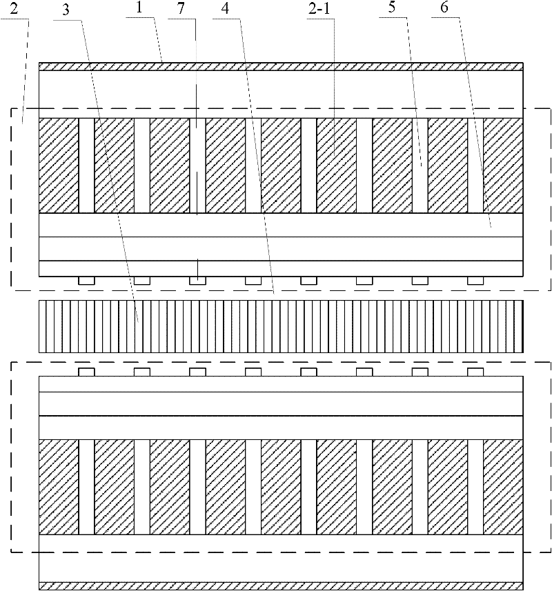
[0017] Specific implementation mode one: the following combination figure 1 and figure 2 This embodiment is described. This embodiment includes a casing 1, a stator 2 and a rotor 3. There is a ventilation area between the inner surface of the casing 1 and the outer surface of the stator 2. The inner surface of the stator 2 is connected to the outer surface of the rotor 3. There is an air gap 4 between the circular surfaces,
[0018] The stator 2 is composed of multi-section stator cores 2-1 arranged at equal intervals. The multi-section stator cores 2-1 are arranged axially along the rotor 3, and a radial ventilation ditch 5 is formed between each adjacent two sections of stator cores 2-1.
[0019] The inner surface of each stator core 2-1 is provided with n stator teeth 2-11 along the circumferential direction, where n is an integer between 50-80,
[0020] It also includes 2n axial partitions 8, and each radial ventilation groove 5 is provided with 2n interdental radial pa...
specific Embodiment approach 2
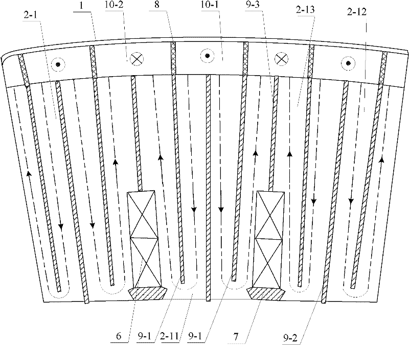
[0026] Specific implementation mode two: the following combination figure 2 and image 3 This embodiment is described. This embodiment is a further limitation of Embodiment 1. The inter-tooth radial partition 9-1 is shorter than the radial partition 9-2 in the cold air zone. Other components and connections are the same as those in Embodiment 1.
[0027] In this embodiment, the length of the radial partition plate 9-2 in the cold air zone along the radial direction of the stator core 2-1 is longer than the length of the radial partition plate 9-1 between the teeth, so that the cold air section 2-12 can be formed. The airflow U-shaped passage that the hot air section 2-13 circulates.
specific Embodiment approach 3
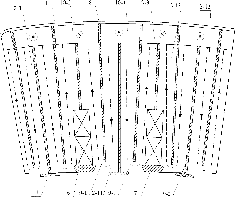
[0028] Specific implementation mode three: the following combination figure 1 and image 3 Describe this embodiment, the difference between this embodiment and the second embodiment is that it also includes n rectangular cold air zone tangential partitions 11,
[0029] The end face of the air gap side of each cold wind zone radial partition 9-2 is fixedly connected to the symmetry line position of a cold wind zone tangential partition 11, and the cold wind zone tangential partition 11 is perpendicular to the cold wind zone radial partition connected thereto 9-2, the tangential partitions 11 of each cold air zone are clamped between two axially adjacent stator teeth 2-11, so that each cold air section 2-12 forms the adjacent hot air section 2-13 U-shaped groove air flow path. Other components and connections are the same as those in Embodiment 2.
[0030] In this embodiment, the tangential partition plate 11 in the cold wind area is used to partially block the U-shaped groov...
PUM
 Abstract
Description
Claims
Application Information
 - Generate Ideas
- Intellectual Property
- Life Sciences
- Materials
- Tech Scout
- Unparalleled Data Quality
- Higher Quality Content
- 60% Fewer Hallucinations
Browse by: Latest US Patents, China's latest patents, Technical Efficacy Thesaurus, Application Domain, Technology Topic, Popular Technical Reports.
© 2025 PatSnap. All rights reserved.Legal|Privacy policy|Modern Slavery Act Transparency Statement|Sitemap|About US| Contact US: help@patsnap.com