
Method for mounting water beam of walking beam heating furnace in thermal state

A technology of walking heating furnace and installation method, which is applied in the direction of lighting and heating equipment, furnace, furnace type, etc., can solve the problem of increasing the investment cost of heating furnace, energy waste, failure to ensure positive pressure of water beam and its column, and difficult Guarantee the verticality of the water beam column, etc., to achieve the effect of good centering size, guaranteed verticality and remarkable effect

Inactive Publication Date: 2011-05-18
ANGANG CONSTR CONSORTIUM
View PDF0 Cites 12 Cited by
  • Summary
  • Abstract
  • Description
  • Claims
  • Application Information

AI Technical Summary

Problems solved by technology

[0006] 1. Due to the need to use external force to pull, it is necessary to ensure that the water beam column has a certain height. If the height is not enough, it is difficult to reserve the amount of stretching in the elasticity. This height directly affects the overall volume of the furnace body and the effective overheating in the furnace. volume
Thus invisibly increasing the investment cost of the heating furnace and the waste of a large amount of energy in the process of use
[0007] 2. It is difficult to guarantee the verticality of the column when the water beam is working in the furnace in the future, so that it cannot be guaranteed that the water beam and its column are really under positive pressure
[0008] 3. It is difficult to carry out process inspection and acceptance during the construction process

Method used


Image

  • Method for mounting water beam of walking beam heating furnace in thermal state
  • Method for mounting water beam of walking beam heating furnace in thermal state
  • Method for mounting water beam of walking beam heating furnace in thermal state

Examples


Embodiment Construction

[0025] The specific embodiment of the present invention will be further described below in conjunction with accompanying drawing:

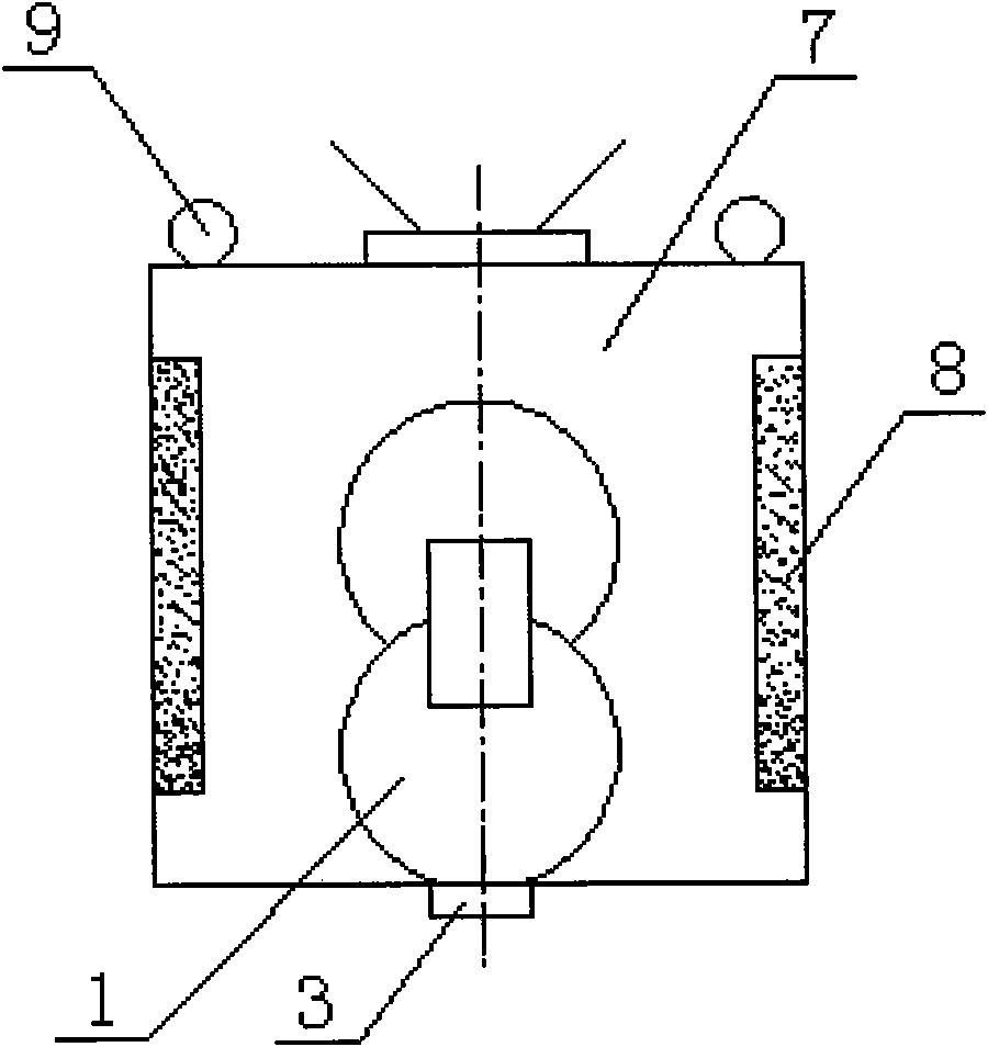
[0026] The hot-state installation method of the water beam of the walking heating furnace uses the heating insulation box and the temperature control system to completely simulate the welding method of the water beam and the column at 273±10°C. The operation steps are as follows:

[0027] 1) Accurately measure the height Δh between the upper beam of the water beam 1 and the tee opening 3, and determine the upper top elevation a of the double pipe 3# column 2 according to the drawings, and confirm that the verticality of the 3# column is within ±1.0mm, and the elevation is at After the deviation is within the range of ±1.0mm, weld the 3# column 2 with the upper support plate 4 and the lower support plate 5;

[0028] 2) Calculate the thermal elongation of the water beam 1 between each tee opening, x=L*λ, where λ is the expansion coefficient, and L i...


PUM


Abstract

The invention relates to a method for mounting a water beam of a walking beam heating furnace in a thermal state, namely a simulated working state. The method is characterized in that: an assembly welding method for the water beam and an upright post at the temperature of 273+ / -10 DEG C is completely simulated through a heating incubator and a temperature control system, and comprises the following operating steps of: 1) determining the verticality and elevation of a double-barreled upright post, and fixedly welding the double-barreled upright post; 2) calculating the heated elongation of the water beam; 3) taking the double-barreled upright post as a center, correspondingly determining center distance among other upright posts according to the elongation, and fixedly welding all the upright posts; 4) correcting out-of-tolerance dimension among the upright posts after finishing the welding; 5) arranging a heating box; 6) heating the water beam, and matching with welding; and 7) keeping the temperature and cooling, wherein the heating box is arranged and controlled in sections. The invention has the advantages that: the service life is obviously prolonged, the welding stress in a cold drawing state is eliminated, and the fabrication error of the water beam can be effectively eliminated in the construction process.

Description

technical field [0001] The invention relates to a method for installing water beams of a walking heating furnace in a hot state, that is, a simulated working state. Background technique [0002] Heating furnace is a large category of industrial furnaces. It refers to the furnace in which the heated materials basically do not undergo physical changes and chemical reactions in the furnace. It is a complex thermal equipment, and the water beam part is the heart of the heating furnace. part. The water beam relies on the orderly movement of the furnace bottom machinery to support the billet to move gradually from the furnace tail to the furnace head inside the heating furnace, and to make the billet reach the specified temperature before being released from the furnace. The working state of the water beam is to work in the furnace at 1250°C. Because of the heat insulation layer, its internal temperature is still working at 273°C. How to solve the expansion problem of the water ...

Claims


Application Information

Patent Timeline
Patent Type & Authority Applications(China)
IPC IPC(8): F27B9/30F27D3/12
Inventor 武振海刘传海邵波尹长生徐世鸿李晓玲王贤权
Owner ANGANG CONSTR CONSORTIUM
Learn More