
Backflow preventer of hand-operated oil pump

The technology of a backflow prevention device and a hand-operated oil pump is applied to the components of the pumping device for elastic fluid, the pump, the piston pump, etc. Easy-to-manufacture, simple-to-construct effects

Inactive Publication Date: 2011-05-11
TAIZHOU BEIRUITE MACHINERY MFG
View PDF0 Cites 5 Cited by
  • Summary
  • Abstract
  • Description
  • Claims
  • Application Information

AI Technical Summary

Problems solved by technology

When it is used again, the negative pressure condition in the pump still needs to be re-established. In addition to slow pumping efficiency, this working condition also causes unnecessary wear and tear on the rotor idling

Method used


Image

  • Backflow preventer of hand-operated oil pump
  • Backflow preventer of hand-operated oil pump

Examples


Embodiment Construction

[0011] The present invention will be further described below according to accompanying drawing.

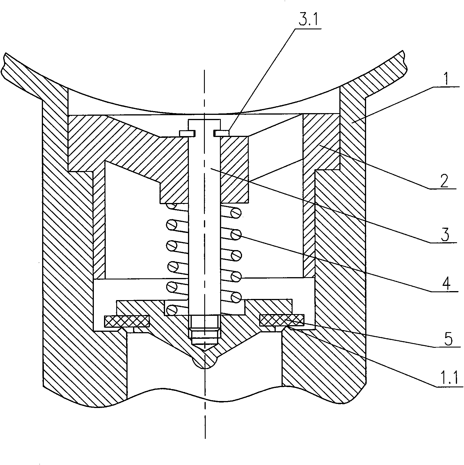
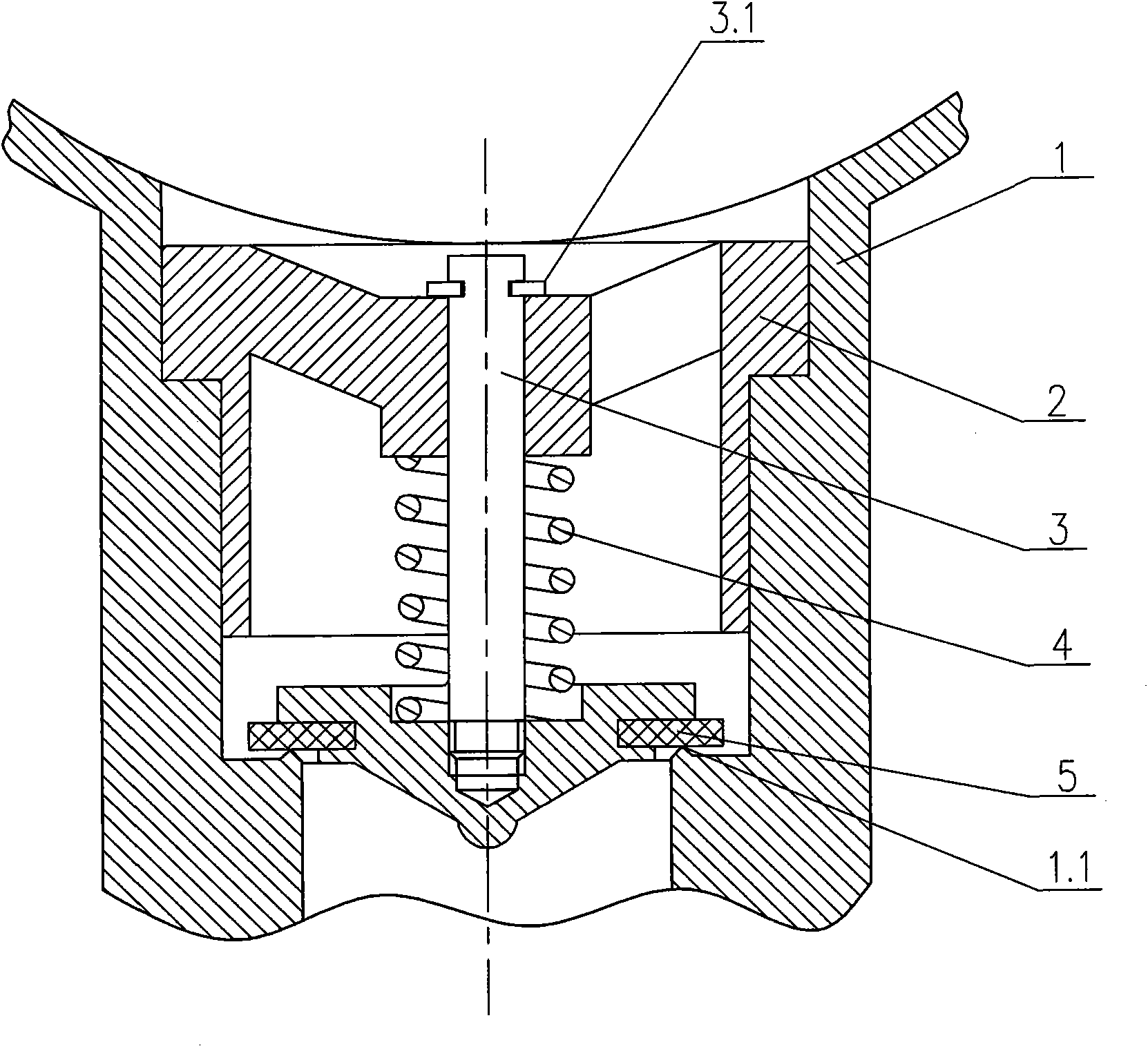
[0012] The anti-backflow device of the hand oil pump shown in the accompanying drawing is located at the oil inlet 1 of the pump and includes a built-in valve seat 2, valve core 3 and spring 4. The pump oil inlet 1 is located at the bottom of the pump body, and its inner hole is stepped. The inlet pipe with the smallest diameter is located at the bottom. The inner end surface of the inlet pipe is provided with an annular step 1.1, and the axial section of the step is an isosceles triangle. The valve seat 2 is cylindrical, and radial ribs are evenly distributed in the inner opening of the big end, and the intersection nodes of the ribs are provided with axial through holes. It passes through the axial through hole with loose fit, and is axially limited by the circlip 3.1, and the rubber flat pad 5 is embedded in the outer frame of the umbrella top facing downward. The above-mentio...


PUM


Abstract

The invention discloses a backflow preventer of a hand-operated oil pump. The backflow preventer is arranged at an oil inlet of the pump, and comprises a built-in valve seat, a valve plug and a spring. An inner hole of the oil inlet of the pump is fitted with the valve seat, the bottom surface of the inner hole is provided with an annular step, and the axial section of the step is in the shape of isosceles triangle. Radial ribs are uniformly distributed at a big-end orifice of the valve seat, and a cross pitch point of the ribs is provided with an axial through hole; and a umbelliform valve-plug shaft section after being sleeved with the spring is in clearance fit with the axial through hole, the valve plug is axially limited by a clamp spring, and a rubber flat mat is embedded into a downward external umbrella frame. Through fitting with the annular step to form a normally closed state, the seal surface is in a line contact mode, which is helpful for separating the valve plug from the annular step under the condition of negative pressure, so that oil can be inhaled successfully. The backflow preventer is good in tightness and flexible in startup, does not affect the oil pumping efficiency, and can prevent the occurrence backflow, therefore, even if the pump stops operating, the pump still stores oil for a long time, so when being used again, the pump can output oil quickly just by shaking the pump for multiple circles by hand.

Description

technical field [0001] The invention relates to a valve device, in particular to a one-way valve device arranged at the oil inlet of a hand-operated oil pump. Background technique [0002] Hand oil pump is a kind of pump product that uses the rotation of the rotor to gradually form a negative pressure condition in the pump body to promote the suction and discharge of oil. It has a simple structure, light weight, and low price. A small amount of oil extraction tool in the warehouse. Although the hand-operated oil pump in the prior art has fully satisfied the use function of pumping oil, it lacks a reliable anti-backflow structure. Some containers. When it is used again, the negative pressure condition in the pump still needs to be re-established. In addition to slow oil pumping efficiency, this working condition also causes unnecessary wear and tear of the rotor idling. Contents of the invention [0003] The present invention achieves technical goals through the followin...

Claims


Application Information

Patent Timeline
IPC IPC(8): F04B53/10F04B9/14
Inventor 刘忠华
Owner TAIZHOU BEIRUITE MACHINERY MFG
Learn More