
Indwelling oxygen supply atomization sputum-aspirating tube

A sputum suction tube and oxygen supply technology, applied in the field of medical devices, can solve the problems of the sputum suction tube affecting the oxygen supply, the high labor intensity of medical staff, and the high expenditure cost, so as to reduce the chances of infection and complications, and reduce work Quantity and labor intensity, cost saving effect

Inactive Publication Date: 2011-05-11
郭维嘉 +1
View PDF5 Cites 1 Cited by
  • Summary
  • Abstract
  • Description
  • Claims
  • Application Information

AI Technical Summary

Problems solved by technology

[0004] 1. Leaving in the trachea will stimulate the secretion of sputum, and the sputum will be concentrated and viscous, even scabbed, and then block the sputum inlet of the sputum suction tube
[0005] 2. The preferred route of the existing sputum suction tube for non-invasive insertion into the trachea is the nasal cavity. However, usually a nasal feeding tube is inserted into one nostril of the patient, and an oxygen delivery tube needs to be inserted into the other nostril for oxygen delivery. The indwelling of the sputum suction tube will inevitably affect the supply of oxygen
Disposable sputum suction tubes are still used for each suction, which still has problems such as high labor intensity and high expenditure costs for medical staff

Method used


Image

  • Indwelling oxygen supply atomization sputum-aspirating tube
  • Indwelling oxygen supply atomization sputum-aspirating tube
  • Indwelling oxygen supply atomization sputum-aspirating tube

Examples


Embodiment Construction

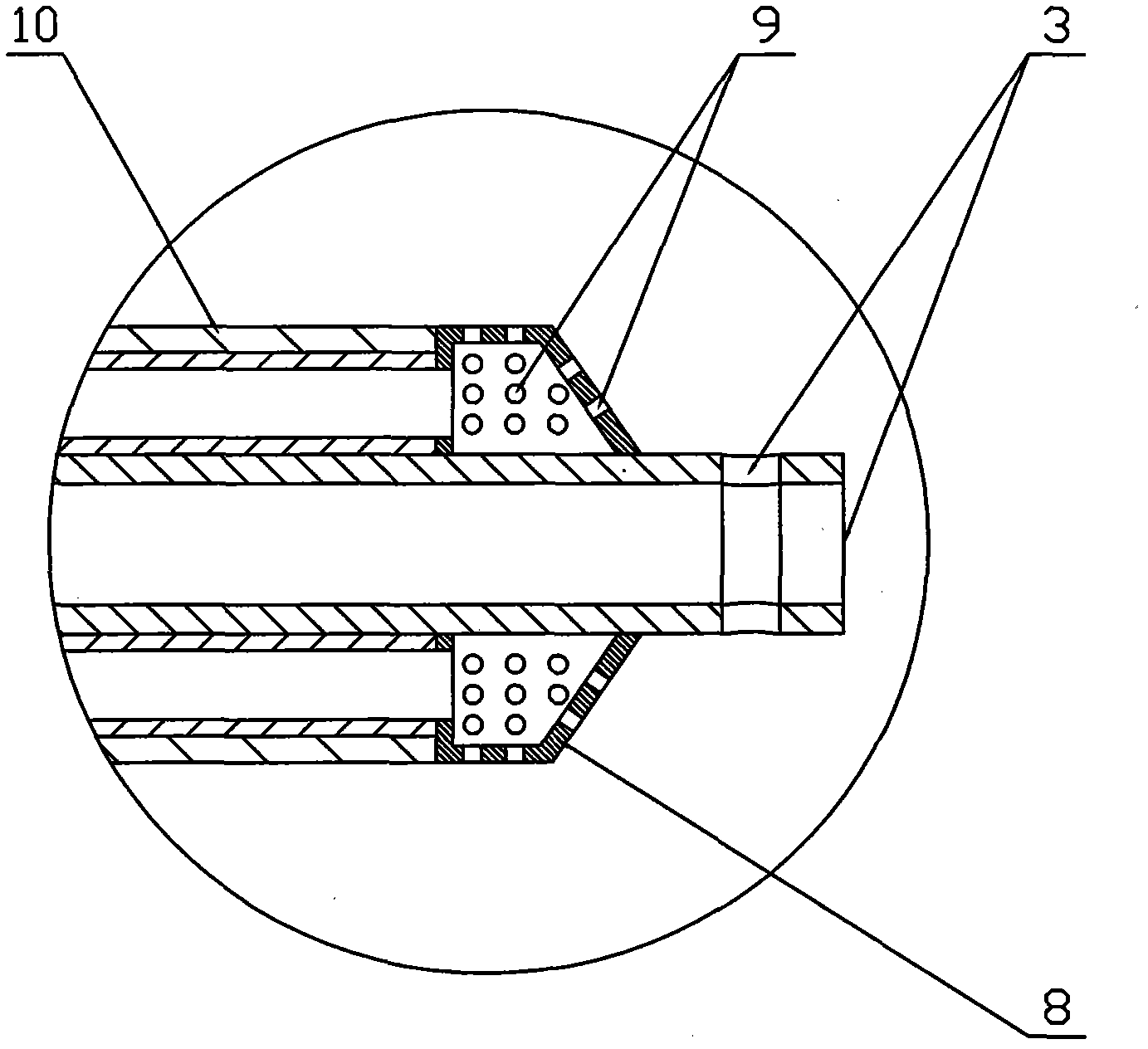
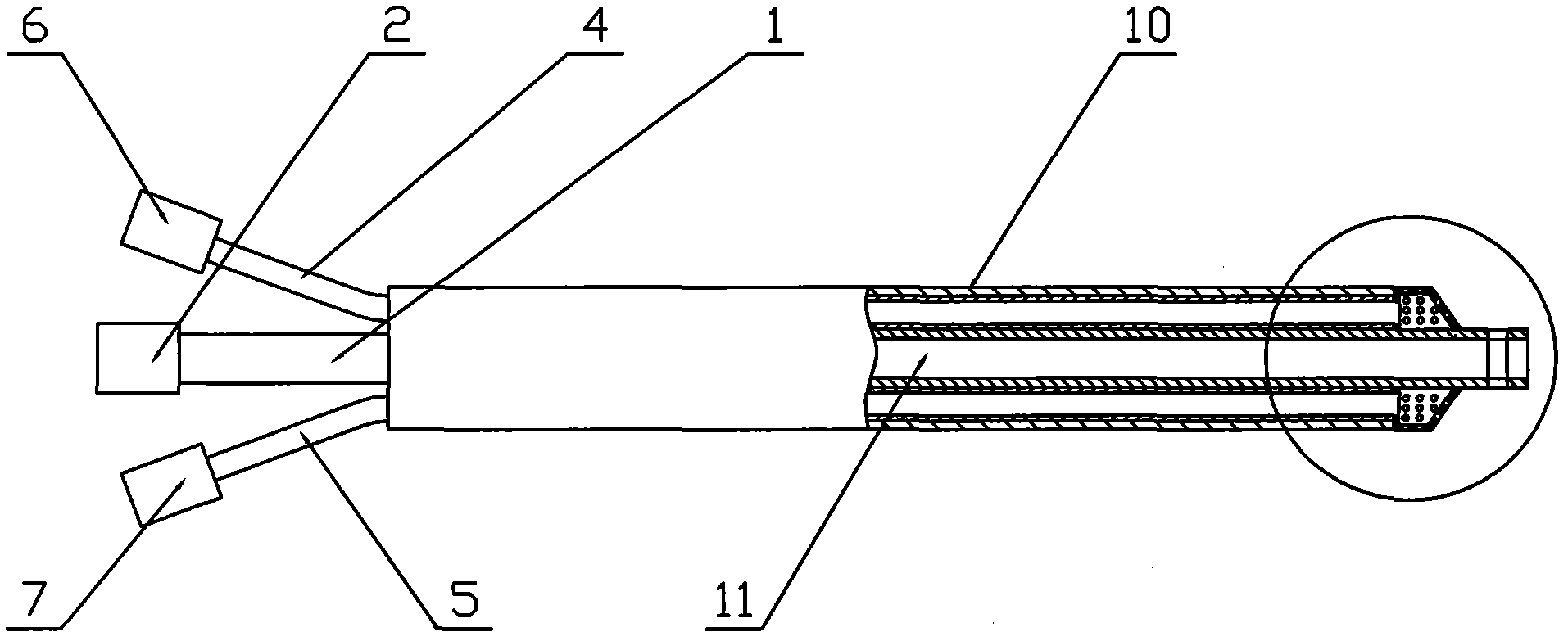
[0013] The specific implementation manner of the present invention will be described below with reference to the accompanying drawings. Such as figure 1 Shown: there is the same sputum suction tube body 1 as the prior art, the rear end of the sputum suction tube body 1 has a negative pressure joint 2, and the front end of the sputum suction tube body 1 has a sputum inlet 3, which is different from the prior art The side wall of the sputum suction tube body 1 is fixed with an air supply pipe 4 and a liquid supply pipe 5, the rear end of the air supply pipe 4 is connected with an air supply joint 6, and the rear end of the liquid supply pipe 5 is connected with a liquid supply joint 7. The sputum tube body 1 is located at the sputum inlet 3 and joined to form an annular tube 8. There are a plurality of atomization micropores 9 on the annular tube 8. The front ends of the air supply tube 4 and the liquid supply tube 5 are placed in the annular tube 8. The sputum suction tube The...


PUM


Abstract

The invention discloses an indwelling oxygen supply atomization sputum-aspirating tube capable of lightening the labor intensity of a medical staff, relieving the pain of a patient and saving the cost expense of a disposable sputum-aspirating tube. The indwelling oxygen supply atomization sputum-aspirating tube is provided with a sputum-aspirating tube body (1), the rear end of the sputum-aspirating tube body (1) is provided with a negative pressure joint (2), and the front end of the sputum-aspirating tube body (1) is provided with a sputum liquid inlet (3). The indwelling oxygen supply atomization sputum-aspirating tube is characterized in that an air supply pipe (4) and a liquid supply pipe (5) are fixed on one side wall of the sputum-aspirating tube body (1), an air supply joint (6) is connected with the rear end of the air supply pipe (4), the rear end of the liquid supply pipe (5) is connected with a liquid supply joint (7), a circular pipe (8) which is arranged at the rear side of the sputum liquid inlet (3) is sleeved on the sputum-aspirating tube body (1), a plurality of atomized millipores (9) are arranged on the circular pipe (8), and the front ends of the air supply pipe (4) and the liquid supply pipe (5) are both arranged in the circular pipe (8).

Description

Technical field: [0001] The invention relates to a medical device, in particular to an indwelling oxygen atomizing sputum suction tube which can reduce the labor intensity of medical staff, relieve pain of patients and save the cost of disposable sputum suction tube. Background technique: [0002] Patients will produce a large amount of sputum in the trachea due to disturbance of consciousness (such as cerebral hemorrhage, brain surgery, coma, etc.), inability to cough up sputum, and severe pneumonia. Methods. [0003] At present, one of the methods of attracting sputum is to use a sputum suction tube to suck sputum. Since the existing sputum suction tube is only a separate tube body (the diameter of the tube is 5 mm), one end of the tube body is provided with a joint for connecting with a negative pressure device. The other end of the tube body is the sputum inlet. For this reason, if it is left in the trachea, the following problems will occur: [0004] 1. Indwelling in ...

Claims


Application Information

Patent Timeline
Patent Type & Authority Applications(China)
IPC IPC(8): A61M25/14A61M11/00A61M16/00
Inventor 郭维嘉张中和
Owner 郭维嘉
Learn More