
Laser diode simulation circuit

A circuit and difference circuit technology, applied in circuits, lasers, laser parts, etc., can solve problems such as long difference, complicated and lengthy calculation process, and difficulty in considering the interaction of lasers and related electronic circuits, so as to facilitate simulation analysis. , the effect of fast and reasonable

Inactive Publication Date: 2012-08-22
SHANDONG UNIV
View PDF1 Cites 0 Cited by
  • Summary
  • Abstract
  • Description
  • Claims
  • Application Information

AI Technical Summary

Problems solved by technology

The usual method of simulating laser diodes in circuits is to obtain I-V characteristics, emitted optical power and injected current P-I curves, transient responses, small signal frequency responses, and nonlinear characteristics by solving the LD rate equation, but the calculation process of this method is complicated. Lengthy, analytical solutions are often obtained under many assumptions, so it is difficult to consider the interaction of the laser and its related electronic circuits, and the conclusions obtained may be far from the actual situation

Method used


Image

  • Laser diode simulation circuit
  • Laser diode simulation circuit
  • Laser diode simulation circuit

Examples


Embodiment 1

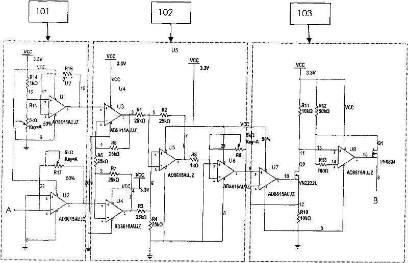
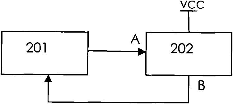
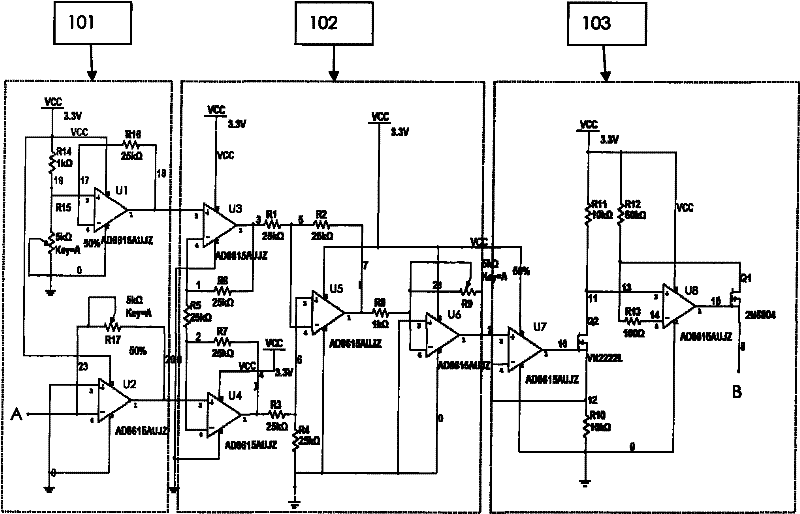
[0018] A circuit that simulates a laser diode, such as figure 1 and figure 2 As shown, 201 is the laser diode automatic power control driving circuit, 202 is the laser diode analog circuit of the present invention, the driving current output by the laser diode automatic power control driving circuit 201 is input to the threshold setting by the A input terminal of the laser diode analog circuit 202 Circuit 101, according to the design principle of voltage difference circuit 102, the input current is converted into the corresponding voltage and compared with the threshold voltage of the laser diode, and the difference between the two is further obtained, and the B output terminal of the laser diode analog circuit 202 is output with The constant current proportional to the difference voltage is used as the power output of the laser diode, and fed back to the laser diode automatic power control driving circuit 201 to adjust the driving current output of the laser diode automatic ...

Embodiment 2

[0020] Embodiment 2: The circuit structure is the same as that of Embodiment 1, the difference is that the models of U1-U8 are AD8616 high-precision operational amplifiers.

Embodiment 3

[0021] Embodiment 3: The circuit structure is the same as that of Embodiment 1, the difference is that the models of U1-U8 are AD8618 high-precision operational amplifiers.


PUM


Abstract

The invention discloses a laser diode simulation circuit, which belongs to the technical field of electronic circuit. The laser diode simulation circuit comprises a threshold setting circuit, a voltage subtractor circuit and a voltage conversion circuit, wherein the threshold setting circuit is used for setting the threshold of the laser diode; the voltage subtractor circuit is used for subtracting the input voltage of the laser diode from a threshold; and the voltage conversion circuit converts the voltage obtained by subtraction into a constant current output in proportion to the voltage.

Description

Technical field: [0001] The invention relates to a circuit for simulating a laser diode, which belongs to the technical field of electronic circuits. Background technique: [0002] With the development of laser technology, laser diodes (LDs) have important applications in many fields such as optical information storage, laser cooling, or as pump light sources for other laser systems due to their advantages of miniaturization, simple structure, and long life. Its output power depends on the size of the input current and the stability of the ambient temperature. The use of laser diodes must be matched with corresponding power control circuits to control the output power of laser diodes to prevent damage to laser diodes due to increased power. In the design process of the laser diode control circuit, the reliability of the circuit is usually obtained through circuit simulation, and then the actual operation is carried out. The usual method of simulating laser diodes in circui...

Claims


Application Information

Patent Timeline
Patent Type & Authority Patents(China)
IPC IPC(8): H01S5/00
Inventor 张飒飒徐海泉
Owner SHANDONG UNIV
Learn More