Bend-resistance multimode optical fiber

A multi-mode optical fiber and anti-bending technology, which is applied in the field of optical communication, can solve the problems of poor anti-bending performance of optical fiber, negative impact of multi-mode bandwidth, and further improvement of optical fiber, and achieve simple and effective manufacturing method and low macrobending additional attenuation , the effect of increasing the bandwidth

Inactive Publication Date: 2011-05-04
YANGTZE OPTICAL FIBRE & CABLE CO LTD
View PDF6 Cites 8 Cited by
  • Summary
  • Abstract
  • Description
  • Claims
  • Application Information

AI Technical Summary

Problems solved by technology

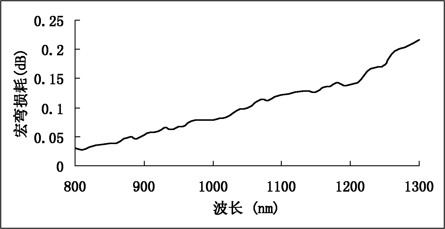
[0003] At present, the more common method to reduce the additional attenuation of optical fiber bending is to adopt the design of the sunken cladding ("trench"). This design has two significant problems. One is that more high-order mode energy will be confined to the boundary of the fiber core. It has a great negative impact on the multimode bandwidth; second, the bending resistance of the fiber will gradually deteriorate with the increase of the wavelength (see attached figure 2 ), the macrobending performance of optical fiber at 1300nm wavelength will be significantly worse than that at 850nm wavelength, which cannot well meet the communication needs of dual windows (850nm and 1300nm)
The previously disclosed Chinese patent CN 101738681A solves the above problems to a certain extent, but the overall bandwidth and macrobending performance of the optical fiber need to be further improved in order to better meet 10Gb / s, 40Gb / s and 100Gb / s high-speed data transmission, and narrow The need for wiring in the environment

Method used


Image

  • Bend-resistance multimode optical fiber
  • Bend-resistance multimode optical fiber
  • Bend-resistance multimode optical fiber

Examples


Embodiment 1

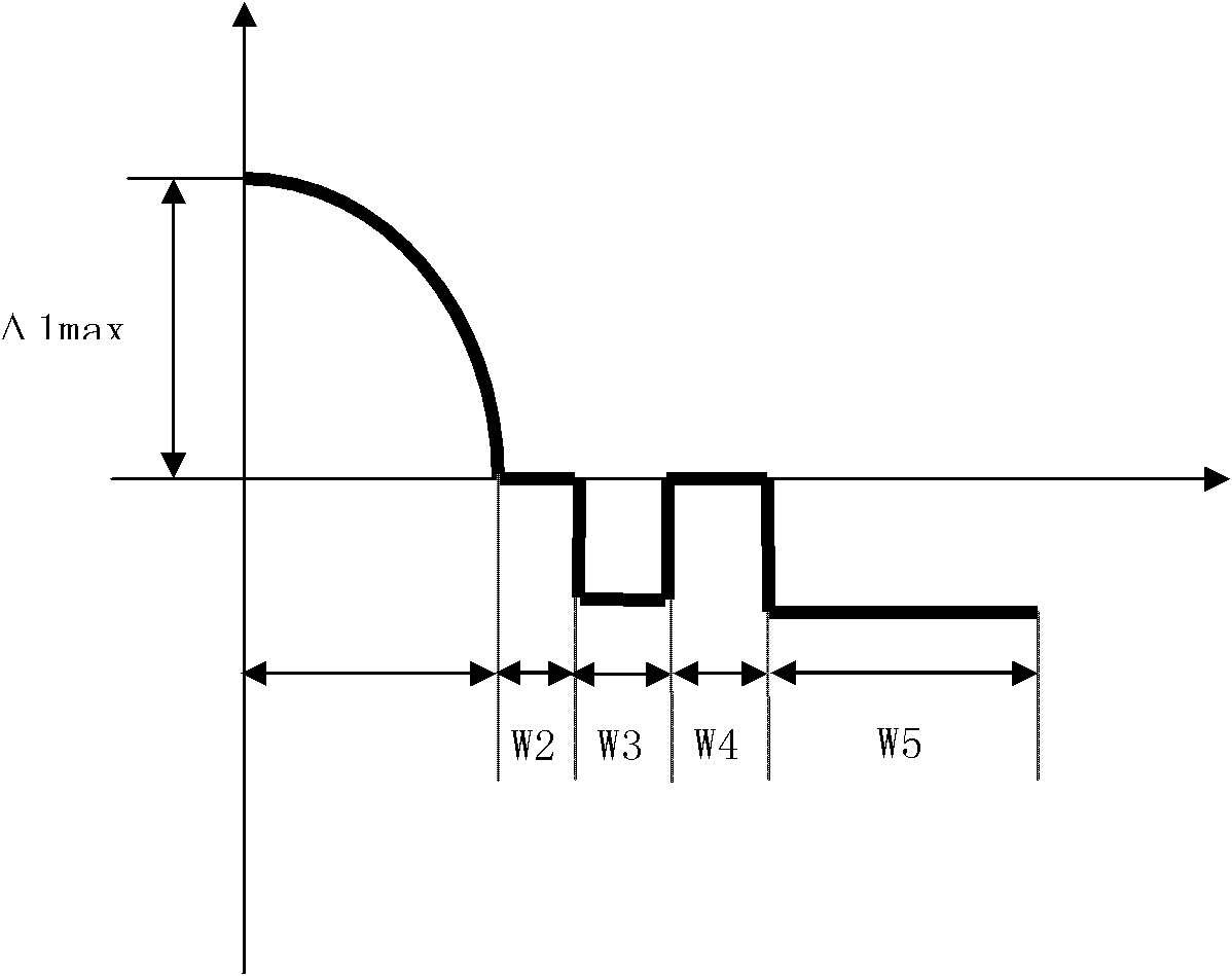
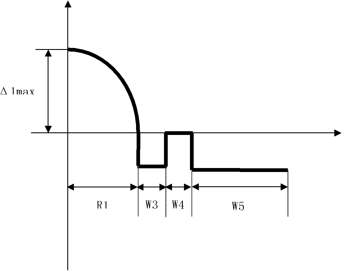
[0048] According to the design of the technical plan (as attached figure 1 Shown), and the manufacturing method of the present invention, prepared a group of prefabricated rods and drawing, adopt the double-layer coating of multimode optical fiber and the drawing speed of 600 m / min, the structure and main performance parameters of optical fiber are shown in Table 1.

[0049] Table 1

[0050]

[0051]

Embodiment 2

[0053] According to the design of the technical plan (as attached figure 2 Shown), and the manufacturing method of the present invention, prepared a group of prefabricated rods and drawing, adopting the double-layer coating of multimode optical fiber and the drawing speed of 600 m / min, the structure and main performance parameters of the optical fiber are shown in Table 2.

[0054] Table 2

[0055]

[0056]


PUM


Abstract

The invention relates to a bend-resistance multimode optical fiber, comprising a core layer and cladding layers. The bend-resistance multimode optical fiber is characterized in that the radius R1 of the core layer is 23-27 microns, the refractive index section of the core layer is a parabola, and the cladding layers outside the core layer successively comprise an inner cladding layer, a sunken ring, a rising ring and a sunken outer cladding layer; the thickness W2 of the single edge of the inner cladding layer is 0-2.5 microns, and the relative refractivity delta 2 of the inner cladding layer is -0.1% to 0.1%; the thickness W3 of the single edge of the sunken ring is 0.5-6 microns, and the minimum relative refractivity delta 3 min of the sunken ring is from -0.1% to -0.3%; the thickness W4 of the single edge of the rising ring is 0.5-10 microns, and the rising ring is a pure silica layer; the thickness W5 of the signal edge of the sunken outer cladding layer is 17-39 microns, and the minimum relative refractivity delta 5 min of the sunken outer cladding layer is from -0.15% to -0.6%; and delta 3 min is larger than delta 5 min. The bend-resistance multimode optical fiber has the characteristics of extremely low macro-bending additional attenuation, has the identical macro-bending property at dual-communication windows (850nm and 1300nm) and macro-bending flat feature; and the refractive index of the sunken ring is higher than that of the sunken outer cladding layer in the optical fibre cladding layer, and the band width of the bending-insensitive multimode optical fiber can be effectively improved.

Description

technical field [0001] The invention relates to a bending-resistant multimode optical fiber used in FTTx, data centers and miniaturized optical devices. The optical fiber has excellent bending resistance and high bandwidth, and belongs to the technical field of optical communication. Background technique [0002] Multimode fiber has been widely used in medium and short-distance fiber optic network systems (such as data centers, local area networks, high-performance computing centers, and storage area networks, etc.). Cabling in indoor and confined environments, especially in applications where excessively long fibers are often wound in increasingly miniaturized storage boxes, is likely to experience tight bend radii. Therefore, it is necessary to design and develop multimode optical fibers with bend-insensitive properties to meet the requirements of indoor optical fiber network laying and device miniaturization. [0003] At present, the more common method to reduce the addi...

Claims


Application Information

Patent Timeline
Patent Type & Authority Applications(China)
IPC IPC(8): G02B6/036G02B6/028
CPCG02B6/0281G02B6/03644G02B6/03672
Inventor 张方海拉吉·马泰倪先元曹蓓蓓罗杰童维军刘泳涛
Owner YANGTZE OPTICAL FIBRE & CABLE CO LTD
Why Eureka
Try Eureka