Brake method of lifting winch/lifting machine for mines and disc-shaped brake

A technology for disc brakes and hoists, applied in the types of brakes, brake components, brake parts, etc., can solve the problems of reducing the service life of the brake shoes, easily soiling the brake disc, and not having a compact structure, so as to save maintenance. Cost, maintenance and replacement of brake shoes are convenient, and the effect of eliminating potential safety hazards

Inactive Publication Date: 2011-05-04
耒阳市湘发环保机械制造有限公司
View PDF4 Cites 10 Cited by
  • Summary
  • Abstract
  • Description
  • Claims
  • Application Information

AI Technical Summary

Problems solved by technology

[0002] At present, the emergency braking of disc brakes in China is controlled by the way that the solenoid valve loses power and returns. There is a potential safety hazard of emergency braking failure after the solenoid valve is stuck. Connect with bolts, and the bolts are made of copper. For this purpose, holes must be drilled on the surface of the brake shoe to install bolts. At least four holes should be drilled for each brake shoe, so that the surface area of ​​each brake shoe can reduce the occupied area of ​​four bolt holes; Secondly, the strength of the brake shoes must be ensured. The depth of the bolt holes must ensure that the brake shoes will not be damaged when the bolts are tightened. Even if the bolts are made of copper, which is lower in hardness than the brake disc, the brake shoes cannot be replaced until the bolts are worn down. tile, thus reducing the service life of the brake shoe, and the structure is not compact, heavy, unsafe, easy to dirty the brake disc

Method used


Image

  • Brake method of lifting winch/lifting machine for mines and disc-shaped brake
  • Brake method of lifting winch/lifting machine for mines and disc-shaped brake

Examples


Embodiment Construction

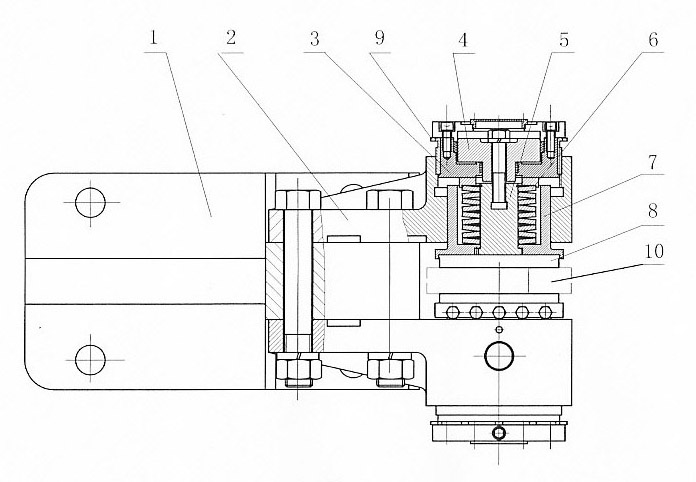
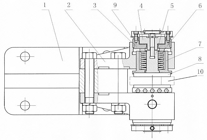
[0015] Such as figure 1 Shown: a mine hoisting winch / hoist disc brake, which is adjusted by a brake leg 1, a support 2, an oil cylinder 3, a piston 4, a guide rod 5, a butterfly spring 6, a brake shoe seat 7 and a brake shoe 8 The screw sleeve 9 is composed of the support 2 on the brake leg 1, the oil cylinder 3 and the brake shoe seat 7 are installed in the inner hole of the support 2, the brake shoe seat 7 can reciprocate along the inner hole of the support 2, the piston 4 and the guide rod 5 is located on the support 2, and the butterfly spring 6 is installed in the brake shoe seat 7 and contacts the outer end surface of the oil cylinder 3. 5mm deep dovetail groove, the adjusting screw sleeve 9 is located between the support 2 and the oil cylinder 3.

[0016] Work process and working principle of the present invention are as follows:

[0017] When the pressure oil enters the oil cylinder 3, the piston 4 pulls up the guide rod 5 to move outward, the guide rod 5 pulls up th...


PUM


Abstract

The invention relates to a disc-shaped brake of a lifting winch / lifting machine for mines, consisting of a brake leg 1, a support 2, a cylinder 3, a piston 4, a guide rod 5, a butterfly-shaped spring 6, a brake shoe seat 7, a brake shoe 8 and an adjusting threaded sleeve 9, wherein the support 2 is positioned on the brake leg 1; the cylinder 3 and the brake shoe seat 7 are arranged in inner holes of the support 2; the piston 4 and the guide rod 5 are positioned on the support 2; the butterfly-shaped spring 6 is arranged in the brake shoe seat 7 and is contacted with the outer end surface of the cylinder 3; and the adjusting threaded sleeve 9 is positioned between the support 2 and the cylinder 3. Since the design is adopted, compared with the prior art, by utilizing the disc-shaped brake, the structure of the disc-shaped brake can be simplified, the cost is reduced, and the potential safety hazard of emergent brake failure after the electromagnet is clamped can be eliminated, so that the maintenance and the replacement of the brake shoe on site are more convenient, the maintenance cost of the brake shoe is saved, the contact area of the brake shoe is increased, and the specific pressure of the brake shoe is reduced, therefore, the utilization ratio of the brake shoe is improved, and the loss of the brake shoe is reduced.

Description

technical field [0001] The invention is an improved braking device, in particular to a braking method and a disc brake of a mine hoisting winch / hoist. Background technique [0002] At present, the emergency braking of disc brakes in China is controlled by the way that the solenoid valve loses power and returns. There is a potential safety hazard of emergency braking failure after the solenoid valve is stuck. Connect with bolts, and the bolts are made of copper. For this purpose, holes must be drilled on the surface of the brake shoe to install bolts. At least four holes should be drilled for each brake shoe, so that the surface area of ​​each brake shoe can reduce the occupied area of ​​four bolt holes; Secondly, the strength of the brake shoes must be ensured. The depth of the bolt holes must ensure that the brake shoes will not be damaged when the bolts are tightened. Even if the bolts are made of copper, which is lower in hardness than the brake disc, the brake shoes cann...

Claims


Application Information

Patent Timeline
Patent Type & Authority Applications(China)
IPC IPC(8): B66D5/14B66D5/28F16D65/24F16D65/04F16D65/48F16D65/22
Inventor 谢湘汇尹毅雄
Owner 耒阳市湘发环保机械制造有限公司
Why Eureka
Try Eureka