
Rotator blade and small electric instrument having rotator blade

A technology of rotating cutter head and cutter head, which is applied in metal processing and other directions, can solve the problems of cracking of electrical insulation film, low yield rate of cutting blade, and poor yield rate, etc., to achieve improved strength, increased cutting opportunities, and efficient beard cutting Effect

Active Publication Date: 2014-08-20
MAXELL HLDG LTD
View PDF11 Cites 0 Cited by
  • Summary
  • Abstract
  • Description
  • Claims
  • Application Information

AI Technical Summary

Problems solved by technology

However, in the process of bending the electroformed master mold into a cylindrical shape, there is a concern that cracks may occur in the electrical insulating film, which may deteriorate the yield when manufacturing the inner blade.
In addition, similarly to the inner bit of Patent Document 2, there is a problem that the angle of the cutting edge is large, and it is difficult to exhibit sharp cutting performance.
[0013] As mentioned above, although the conventional inner cutter head with the inner cutter body formed by the etching method or the electroforming method as the cutting element is simpler in structure than the inner cutter head with the spiral cutter head as the cutting element, it is difficult to obtain a good yield in the case of low yield. There is still room for improvement in the aspect where it is difficult to sharpen the cutting edge

Method used


Image

  • Rotator blade and small electric instrument having rotator blade
  • Rotator blade and small electric instrument having rotator blade
  • Rotator blade and small electric instrument having rotator blade

Examples


Embodiment Construction

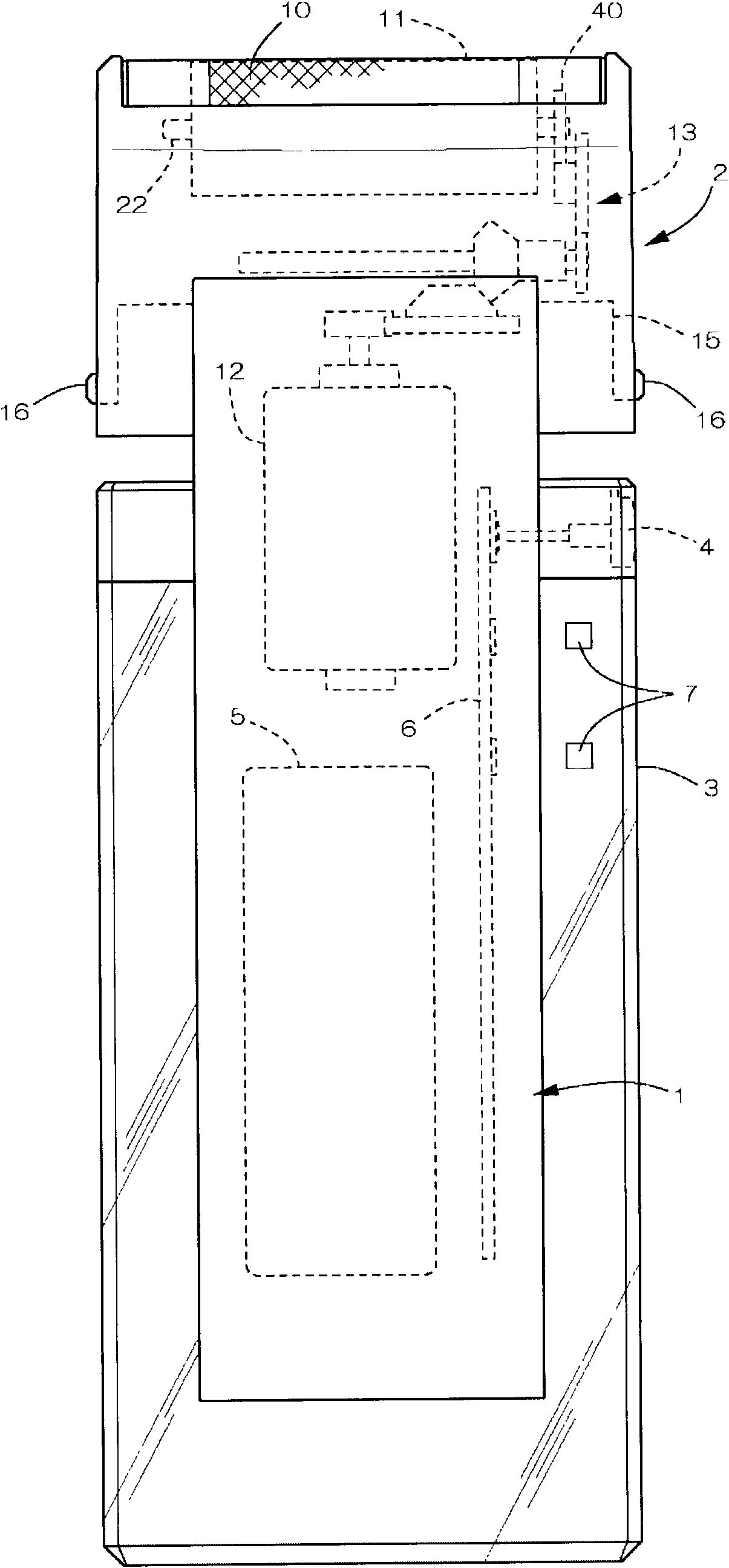
[0063] Figure 1 to Figure 11 An example in which the rotary head of the present invention is used for an inner head of a rotary electric shaver is shown. exist figure 2 Among them, the electric shaver includes: a main body 1, a head 2 supported by the main body 1, an outer frame 3 mounted on the main body 1, a shaving unit (not shown) disposed on the rear side of the main body 1, and the like. The outer frame 3 doubles as a decorative frame, and cooperates with the main body 1 to form a handle of the electric shaver. On one upper end of the outer frame 3, a switch button 4 for turning the motor 12 on and off is provided.

[0064] A rechargeable battery 5 and a circuit board 6 are installed inside the main body 1, and a switch for switching operation by the above-mentioned switch button 4, an LED for a display lamp 7, and a circuit composed of a control circuit and a power supply circuit are installed in the circuit board 6. electronic components, etc.

[0065] In head 2,...


PUM


Abstract

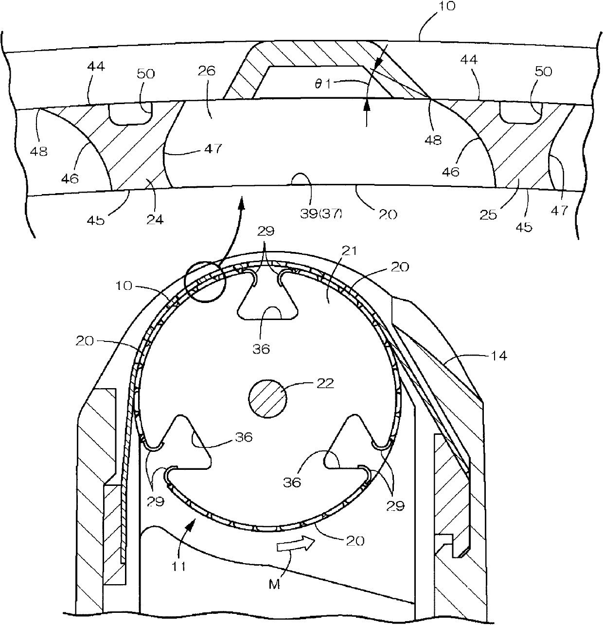
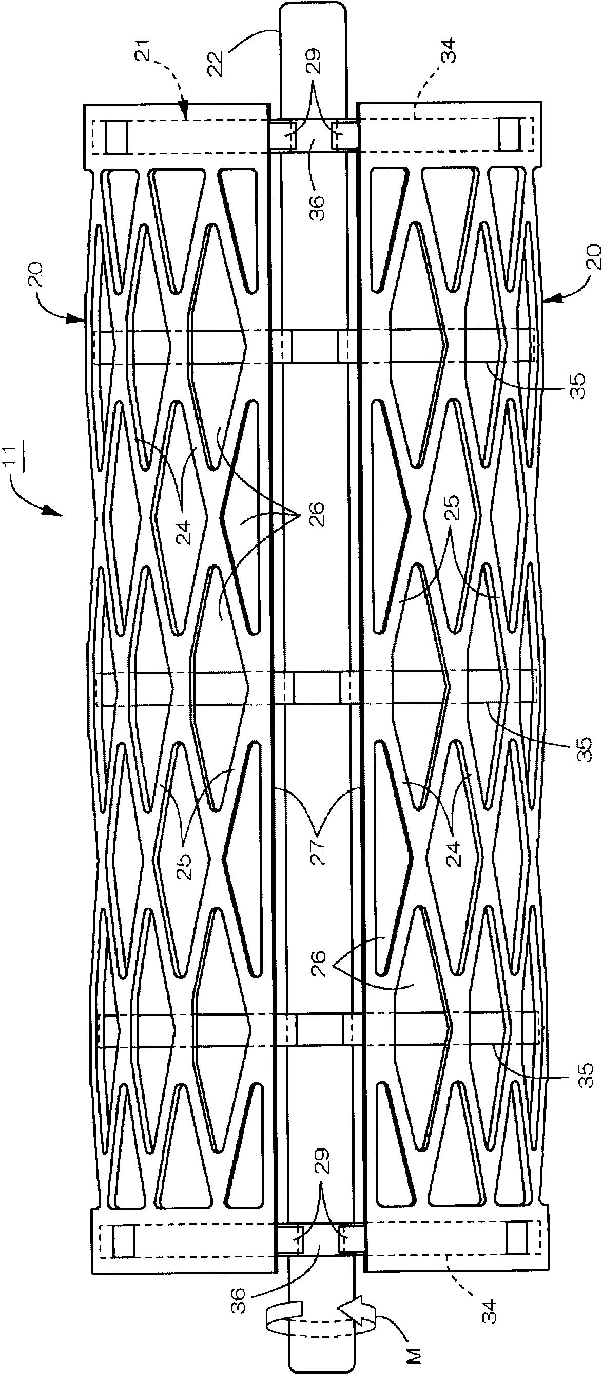
The present invention provides a rotary blade and a small electric instrument having the rotator blade, wherein the rotator blade which can effectively introduce and efficiently cut off the beard and has easy cleaning of flock is provided. The rotator blade which comprises a blade body and a blade bracket that supports the blade body is composed. Etching treatment is performed for stainless steel plate thereby forming a group of rib-shaped small cutting edge and a group of cutting blade holes in the blade body. A plurality of blade bodies are fixed on a circumferential surface of the blade bracket and the rotator blade is composed to a cylinder shape. Each small cutting edge is provided with the following components: a cutting surface of an external surface; a non-cutting surface of an inner surface; a side edge part for connecting the cutting surface with the non-cutting surface; a cutting edge which is formed at an upstream side in a rotation direction of the cutting surface; and a back clearance surface edge which is formed at the downstream side in the rotation direction of the cutting surface. A width center of the non-cutting surface deviates from a width center of the cutting surface to the downstream side of the rotation direction. A cutting edge angle of the cutting edge, which is smaller than an edge angle of the back clearance surface edge, is formed.

Description

technical field [0001] The present invention relates to a rotary head used for a rotary electric razor, a hair remover, etc., and a small electric appliance equipped with the rotary head. The cutter head main body constituting the inner cutter head is formed by etching, electroforming, and press processing. Background technique [0002] The inner cutter head (rotary cutter head) in a general rotary electric razor includes more than a dozen helical cutter heads, a circular shaft-shaped inner cutter head support body formed by plastic, and a metallic one embedded in the inner cutter head support body. Inner cutter shaft (Patent Document 1). The helical cutter head is inserted and fixed when the inner cutter head support body is formed, so that it is integrated with the inner cutter head support body. The formed helical bit is ground to form a cutting edge at the tip of the bit. Since the cutting blades are continuous in a spiral shape, it is possible to break the hairs that...

Claims


Application Information

Patent Timeline
Patent Type & Authority Patents(China)
IPC IPC(8): B26B19/16
CPCB26B19/00B26B19/14B26B19/16B26B19/38
Inventor 八寻伸纪岩仓幸太郎
Owner MAXELL HLDG LTD
Learn More