Integrated control circuit of LED (light-emitting diode)

A technology of integrated control and circuit, applied in the direction of electric lamp circuit layout, electric light source, lighting device, etc., can solve the problems of LED lamp turn-on, turn-off and dimming time inconsistency, complicated circuit, lower reliability, etc., and achieve a wide range Effect of dimming, reduction of harmonic pollution, and reduction of conduction loss

Inactive Publication Date: 2011-04-27
陈艳艳
View PDF2 Cites 2 Cited by
  • Summary
  • Abstract
  • Description
  • Claims
  • Application Information

AI Technical Summary

Problems solved by technology

Since the LED power supply adopts high-efficiency, wide-range input voltage AC / DC high-frequency switching power supply, the traditional linear adjustment of input voltage or phase-controlled voltage regulation can no longer adjust the output voltage or current, and cannot realize the brightness adjustment of LED lights.
At present, there are many ways of dimming: some use automatic timing dimming in the LED driver, that is, when the lamp is on for a certain period of time, the brightness will be lowered. This control method requires each LED lamp to have an ambient brightness detection device. And timing dimming circuit, and the turn-on, turn-off and dimming time of each LED light are not uniform, and the entire lighting system is not controllable
It is also possible to add a control circuit that can receive wireless signals or power carrier signals to the power supply, and then send signals through the central controller to centrally control the brightness of the LED lighting system, but this method is costly, complicated and less reliable.

Method used


Image

  • Integrated control circuit of LED (light-emitting diode)
  • Integrated control circuit of LED (light-emitting diode)
  • Integrated control circuit of LED (light-emitting diode)

Examples


Embodiment

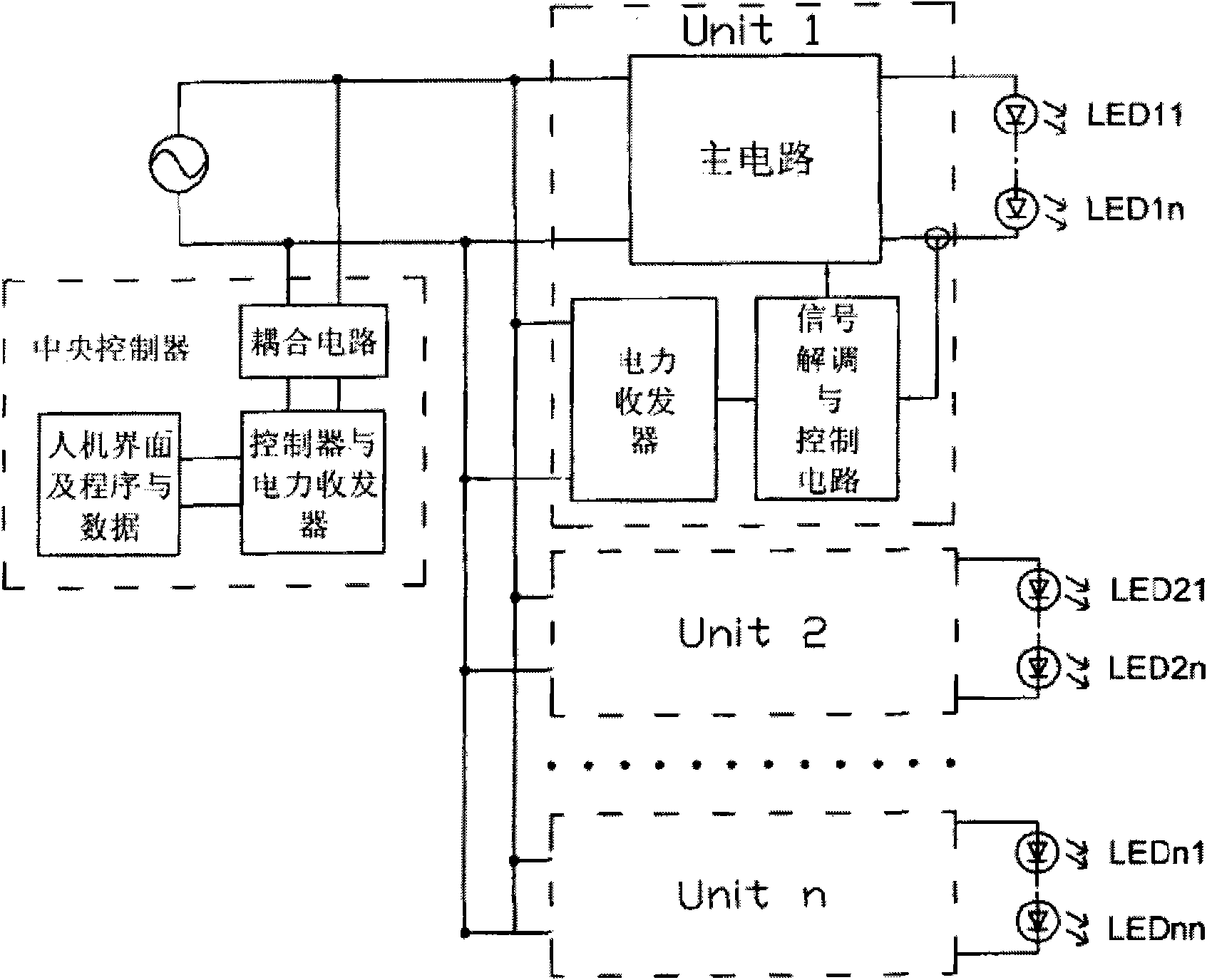
[0026] Example: refer to Figure 2-4 , the LED integrated control circuit of the present invention includes a central controller and a multi-channel LED drive circuit, the central controller includes an EMI filter, a bidirectional control thyristor SCR and a dimming control trigger circuit, and the thyristor SCR is adjusted by The dimming control trigger circuit triggers the conduction phase angle and sends out a dimming control signal; the dimming control trigger circuit includes a manual brightness adjustment trigger circuit, and / or an ambient brightness detection and brightness adjustment trigger circuit, and / or a timing control adjustment Trigger circuit to output manual, light-controlled and / or time-controlled dimming signals;

[0027] Each LED drive circuit includes a main circuit, a signal detection shaping and conversion circuit, a current adjustment and constant current control circuit, the main circuit accepts the control of the current adjustment and constant curren...


PUM


Abstract

The invention discloses an integrated control circuit of an LED (light-emitting diode), comprising a central controller and multiple paths of LED driver circuits, wherein the central controller comprises a silicon controlled rectifier (SCR) and a dimming control trigger circuit; the dimming control trigger circuit comprises a manual luminance regulation trigger circuit and / or an environmental luminance detection and luminance regulation trigger circuit and / or a timing control and regulation trigger circuit and is used for outputting manual, light-operated and / or time-control dimming signals; and each LED driver circuit comprises a main circuit, a signal detection, reshaping and conversion circuit and a current regulation and constant-control circuit. The dimming effect within a wider range can be obtained when the conduction angle of the SCR in a central controller changes within a small range; and in addition, the invention has simple circuit and low cost, does not generate large harmonic wave and can lower the possibility of harmonic wave pollution.

Description

technical field [0001] The invention relates to a dimming circuit of an LED lighting system. Specifically, it should be a LED integrated control circuit. Background technique [0002] With the increasing energy consumption, the requirements for energy saving are also getting higher and higher, and lighting electricity consumption is an important part of people's energy consumption. As an energy-saving and green lighting method, new LED lighting will replace traditional gas discharge lamps and incandescent lamps. LED has long service life, high luminous efficiency, and can save a lot of electric energy, and the driving and control method of LED is simple, which is convenient for flexible adjustment of luminous brightness, especially suitable for some applications where luminous brightness needs to be adjusted according to different situations, such as street lamps, squares, etc. Public places and indoor lighting systems. Especially for a lot of road lighting, there are few...

Claims


Application Information

Patent Timeline
Patent Type & Authority Applications(China)
IPC IPC(8): H05B37/02
Inventor 陈艳艳
Owner 陈艳艳
Why Eureka
Try Eureka