Eureka AIR delivers breakthrough ideas for toughest innovation challenges, trusted by R&D personnel around the world.

Damping coupling

A technology of couplings and damping springs, applied in the direction of couplings, elastic couplings, mechanical equipment, etc., can solve the problem that rigid couplings cannot absorb the vibration and shock of motors and transmissions, and reduce the reliability of motors and transmission system components Sex and life, the reliability of ordinary elastic couplings, and the axial and radial dimensions cannot be directly selected to achieve the effects of avoiding vibration damping compression deformation, superior performance, and stable damping

Inactive Publication Date: 2011-04-27
力帆科技(集团)股份有限公司
View PDF4 Cites 9 Cited by
  • Summary
  • Abstract
  • Description
  • Claims
  • Application Information

AI Technical Summary

Problems solved by technology

With the increasingly rich theory of electric vehicles, the transmission is replaced by a two-speed or multi-speed transmission with automatic shifting, and the shifting inevitably produces shocks, and the rigid coupling cannot absorb the vibration generated during work between the electric motor and the transmission impact; moreover, the vibration of the transmission system itself will also have an adverse effect on the motor, and will also reduce the reliability and life of the motor and transmission system components
Due to the compact structure of electric vehicles, various types of ordinary elastic couplings cannot be directly selected due to reliability and axial and radial dimensions.

Method used


Image

  • Damping coupling
  • Damping coupling
  • Damping coupling

Examples


Embodiment Construction

[0017] Below in conjunction with accompanying drawing and embodiment the present invention will be further described:

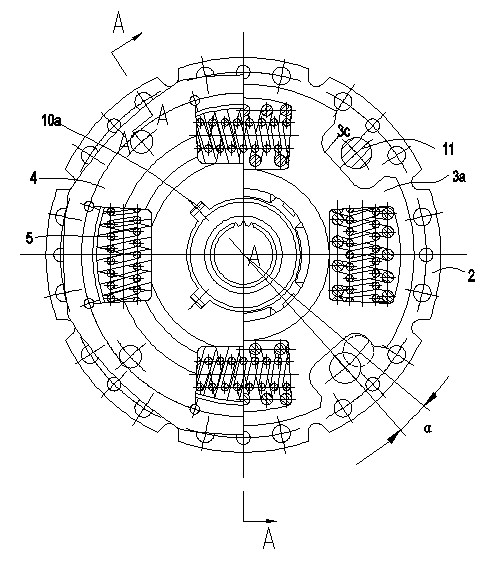
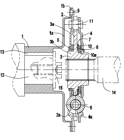
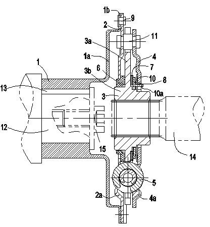
[0018] Such as figure 1 , 2 A vibration-damping coupling shown is composed of a flange 1 , a driven plate 2 , a hub 3 , a vibration-damping disk 4 and a vibration-damping spring 5 . The flange plate 1, the driven plate 2, the disc hub 3 and the damping plate 4 are all disc structures and coaxially installed. The inner hole of the flange 1 is a flat key hole, and the flange 1 is set on the motor output shaft 12 through the flat key 13; the right end of the flange 1 extends outward to form an opening 1a, and the outer edge of the opening 1a has a The outer flange 1b perpendicular to the axis of the disc 1 is connected to the driven piece 2 by first rivets 9, and the first rivets 9 are evenly distributed on the circumference. The hub 3 is composed of a hub web 3a and a hub core 3b. The inner hole of the hub core 3b is a spline hole. The hub core 3b is set on ...


PUM


Abstract

The invention discloses a damping coupling which comprises a flange plate, a driven piece, a disk hub, a damping disk and damping springs, wherein the flange plate is connected with the driven piece through a first rivet; the disk hub consists of a disk hub web plate and a disk hub core plate; a disk hub core at the left side of the disk hub web plate is sleeved with a first damping washer; a disk hub core at the right side of the disk hub web plate is sequentially sleeved with a second damping washer, a positioning washer, a butterfly-shaped spring and a damping disk from left to right; the driven piece, the disk hub web plate and the damping disk are provided with elongated holes in corresponding positions in the circumferential direction; the damping springs are arranged in the elongated holes; the driven piece, the disk hub and the damping disk are connected through a second rivet; and the disk hub can rotate an angle alpha relative to the driven piece and the damping disk. The invention can effectively cut down the gear shift impact of a transmission, reduce adverse effects of the vibration of a transmission system on an electromotor and improve the reliability and the service life of the electromotor and parts of the transmission system.

Description

technical field [0001] The invention relates to the technical field of automobiles, in particular to a vibration-damping coupling used in electric automobiles, which is used for coupling between electric motors and transmissions. Background technique [0002] The connection between the electric motor and the transmission of an electric vehicle generally adopts a rigid coupling, because it does not need to shift gears, there is no impact vibration caused by shifting, and the vibration of the transmission system has less obvious influence on the motor. With the increasingly rich theory of electric vehicles, the transmission is replaced by a two-speed or multi-speed transmission with automatic shifting, and the shifting inevitably produces shocks, and the rigid coupling cannot absorb the vibration generated during work between the electric motor and the transmission Impact; moreover, the vibration of the transmission system itself will also have an adverse effect on the motor, ...

Claims


Application Information

Patent Timeline
IPC IPC(8): F16D3/12
Inventor 周达云
Owner 力帆科技(集团)股份有限公司
Why Eureka
Eureka Blog
Learn More