Screw pile used for seasonally frozen ground zone

A screw pile, seasonal technology, applied in the field of screw piles, can solve the problems of not being able to effectively prevent and control frozen soil damage, and achieve the effect of large bearing capacity, reduced size, and fast pile formation

Inactive Publication Date: 2012-07-25
HARBIN INST OF TECH
View PDF0 Cites 0 Cited by
  • Summary
  • Abstract
  • Description
  • Claims
  • Application Information

AI Technical Summary

Problems solved by technology

[0005] In order to solve the problem that the current prefabricated screw piles cannot be effectively prevented from damage to buildings (structures) due to freezing damage such as frost heave and thawing settlement when the prefabricated screw piles are used in seasonally frozen soil areas, the present invention provides a seasonal Spiral piles in permafrost regions

Method used


Image

  • Screw pile used for seasonally frozen ground zone
  • Screw pile used for seasonally frozen ground zone

Examples


specific Embodiment approach 1

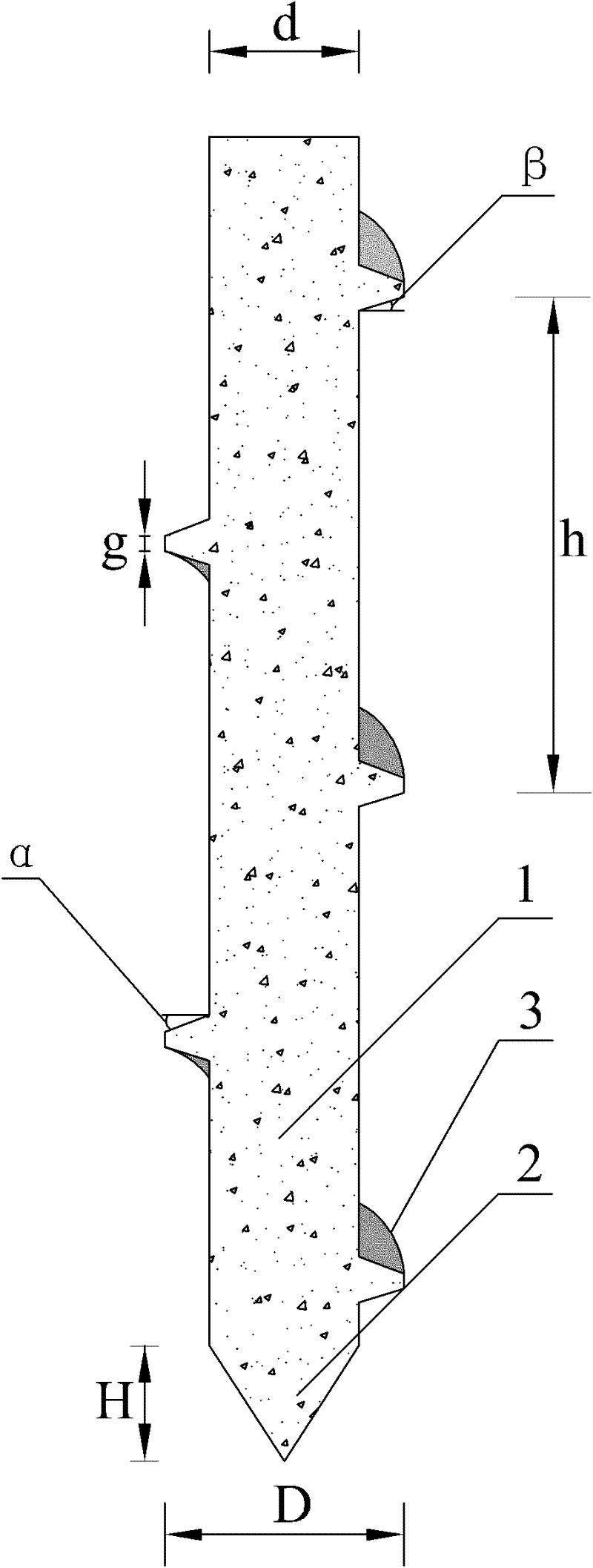
[0009] Specific implementation mode one: combine figure 1 Describe this embodiment, the screw pile of this embodiment comprises concrete pile body 1, concrete pile head 2 and concrete spiral blade 3, concrete pile body 1 is cylindrical, concrete pile head 2 is a cone, the bottom end surface of concrete pile body 1 It is affixed to the upper end surface of the concrete pile head 2 and the two are integrated, and the concrete spiral blade 3 is arranged on the outer wall of the concrete pile body 1, and the two are integrated, and the upward inclination angle α of the concrete spiral blade 3 is 15 to 45 °, the screw pitch h is 800 mm to 1000 mm, and the ratio of the diameter d of the concrete pile body 1 to the outer diameter D of the concrete spiral blade 3 is 0.5 to 0.7.

[0010] With the increase of the screw pitch, the vertical displacement value of the pile top under the action of the freezing pullout force of the screw pile increases continuously, based on the actual situat...

specific Embodiment approach 2

[0012] Specific implementation mode two: combination figure 1 Describe the present embodiment, the ratio of the diameter d of the concrete pile body 1 of the present embodiment and the outer diameter D of the concrete spiral blade 3 is 0.6, and the vertical displacement value of the frozen-drawn spiral pile is minimum at this moment, and it is in the seasonal permafrost region It can most effectively prevent the damage to buildings (structures) caused by frost heaving, thawing and settlement of frozen soil. Other components and connections are the same as those in the first embodiment.

specific Embodiment approach 3

[0013] Specific implementation mode three: combination figure 1 To illustrate this embodiment, the thread thickness g of the concrete spiral blade 3 of this embodiment is 80 mm to 120 mm. This structure can most effectively prevent frost damage such as frost heaving and thawing of the frozen soil in areas with seasonally frozen soil. ) destruction of buildings. Other components and connections are the same as those in the first embodiment.


PUM


Abstract

The invention relates to a screw pile used for a seasonally frozen ground zone, belonging to a screw pile and aiming at solving the problems of a certain limit of application range, easy breaking, no guarantee of pile body quality and high engineering cost of the traditional linear pile in the seasonally frozen ground zone at present. The screw pile comprises a concrete pile body, a concrete pilehead and a concrete screw blade, wherein the concrete pile body is cylindrical, the concrete pile head is shaped as a cone, the bottom end face of the concrete pile body and the upper end face of theconcrete pile head are fixedly connected and made into a whole, the concrete screw blade is arranged on the outer wall of the concrete pile body, the concrete screw blade and the concrete pile body are made into a whole, the upper inclination of the concrete screw blade is 15-45 DEG, the pitch of the concrete screw blade is 800-1,000mm, and the ratio of the diameter of the concrete pile body to the outer diameter of the concrete screw blade is 0.5-0.7. The invention is used for the pile foundation of the seasonally frozen ground zone.

Description

technical field [0001] The invention relates to a screw pile. Background technique [0002] With the development of the economy, the amount of engineering in seasonally frozen soil areas has gradually increased, and the hazard of frost heave in frozen soil has always been an engineering problem. At present, the engineering measures for the prevention and control of freezing damage in seasonal frozen soil areas mainly include: dynamic compaction to strengthen foundation soil, replacement of foundation soil, EPS foam insulation board, weakening the interaction between soil and foundation, etc. Although these commonly used antifreeze engineering measures have reduced the frost heaving disaster to a certain extent, the engineering quantity brought thereby is large, and the engineering cost is also very high. [0003] In seasonally frozen soil areas, in order to prevent frost heave deformation more effectively, improving the foundation form of buildings in frozen areas is a dire...

Claims


Application Information

Patent Timeline
Patent Type & Authority Patents(China)
IPC IPC(8): E02D5/56E02D27/35
Inventor 汤爱平涂杰文陈然
Owner HARBIN INST OF TECH
Why Eureka
Try Eureka