Eureka AIR delivers breakthrough ideas for toughest innovation challenges, trusted by R&D personnel around the world.

Concrete pile forming device and construction method thereof

A technology for concrete piles and construction methods, applied in sheet pile walls, infrastructure engineering, construction, etc., can solve the problems of complex construction, increased cost, and reduced work efficiency, and achieves good pile quality, high work efficiency, and low engineering cost. Effect

Inactive Publication Date: 2014-12-24
王继忠
View PDF12 Cites 12 Cited by
  • Summary
  • Abstract
  • Description
  • Claims
  • Application Information

AI Technical Summary

Problems solved by technology

At present, some literatures have proposed the combination of the above two kinds of piles, but the construction process is to first form the cement-soil pile, and then form holes in the cement-soil pile again and carry out the construction of the pile body again, so multiple equipments are required Rotation is carried out, so the construction is complicated, the work efficiency is reduced, and the cost is increased

Method used


Image

  • Concrete pile forming device and construction method thereof
  • Concrete pile forming device and construction method thereof

Examples


Embodiment Construction

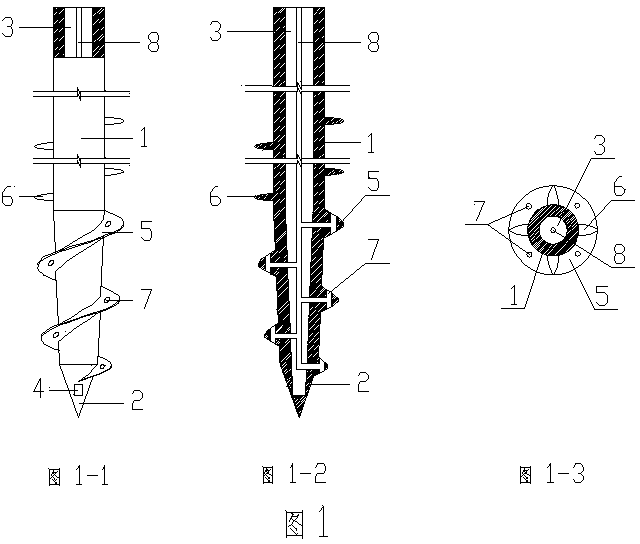
[0023] figure 1 It is the structural diagram of the pile forming device of the concrete pile of the present invention, as figure 1 As shown, the piling device includes a drill pipe 1 and a drill bit 2, the lower end of the drill bit 2 is provided with a discharge port 4, the inside of the drill pipe 1 is a hollow pipe 3 that can transport concrete, and the hollow pipe 3 is provided with a pipe that can transport cement slurry. Slurry pipe 8, the upper part of the outer wall of the drill pipe 1 is a straight rod, the middle part is provided with a plurality of stirring blades 6, and the lower part is provided with continuous helical blades 5. A plurality of slurry outlet holes 7 are arranged on the top, the slurry outlet holes 7 communicate with the slurry delivery pipe 8, and the hollow pipe 3 communicates with the discharge port 4 at the lower end of the drill bit 2 .

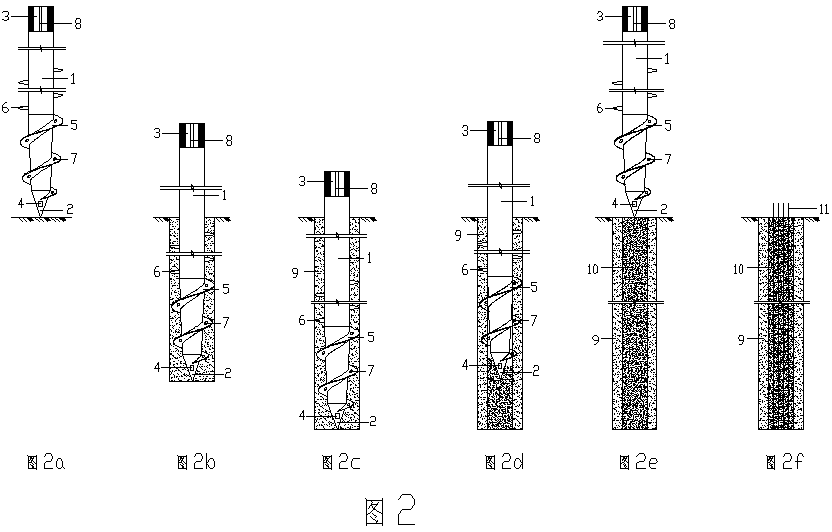
[0024] figure 2 It is the operation figure of the construction method of the concrete pile of an embodim...


PUM


Abstract

The invention aims at providing a concrete pile forming device. The concrete pile forming device is characterized in that the internal part of a drill rod is a hollow pipe, a grout supply pipe is arranged in the hollow pipe, the upper section of the outer wall of the drill rod is a straight rod, the middle section is provided with an agitating blade, the lower section is provided with a helical blade and the helical blade is provided with mortar outlets. The invention further provides a concrete pile construction method of the above-mentioned pile forming device. The concrete pile construction method comprises the following steps: 1) aligning the pile forming device to a pile position; 2) supplying cement grout into the grout supply pipe to inject into a soil body while drilling a soil layer through a drill bit and the helical blade, conducting forcible agitation through the helical blade and the agitating blade; 3) continuing until preset design depth is reached; 4) supplying concrete into the hollow pipe to fill the central part of a cement-soil pile body; 5) reversely rotating and upwards lifting the drill rod while supplying the concrete, and forming a concrete reinforcing body with certain diameter in the center of the cement-soil pile body; 6) conducting subsequent construction according to the structural form of a foundation.

Description

technical field [0001] The invention relates to the field of civil engineering, in particular to the construction of piles. Background technique [0002] Among the current foundation treatment methods in our country, it is common to make cement-soil piles by deep mixing or high-pressure rotary spraying. Its advantage is that it does not take soil and makes good use of the original soil. Due to the limitation of the material, the strength of the pile body is small; the concrete pile is also a kind of pile type widely used. This method can combine the advantages of the two kinds of piles to improve its overall ultimate bearing capacity. At present, some literatures have proposed the combination of the above two kinds of piles, but the construction process is to first form the cement-soil pile, and then form holes in the cement-soil pile again and carry out the construction of the pile body again, so multiple equipments are needed Rotation is carried out, thus resulting in co...

Claims


Application Information

Patent Timeline
IPC IPC(8): E02D5/36E02D5/46E02D15/04
Inventor 王继忠
Owner 王继忠
Why Eureka
Eureka Blog
Learn More