Eureka AIR delivers breakthrough ideas for toughest innovation challenges, trusted by R&D personnel around the world.

Roll-to-roll distance measuring device

A technology of measuring device and roller interval, which is applied in the direction of measuring device, mechanical gap measurement, using optical device, etc., can solve the problems of difficult to grasp the peak value of displacement and the decrease of measurement accuracy, so as to suppress the bite of foreign objects, ensure soundness, The effect of high-precision measurement

Active Publication Date: 2013-07-24
NIPPON STEEL CORP +1
View PDF4 Cites 0 Cited by
  • Summary
  • Abstract
  • Description
  • Claims
  • Application Information

AI Technical Summary

Problems solved by technology

However, in this case, the vertical motion of the head 103b becomes small, so it is difficult to grasp the peak value of the displacement amount that can be detected by the head 103b, and the problem of lowering the measurement accuracy occurs.

Method used


Image

  • Roll-to-roll distance measuring device
  • Roll-to-roll distance measuring device
  • Roll-to-roll distance measuring device

Examples


Embodiment Construction

[0085] Hereinafter, preferred embodiments of the present invention will be described.

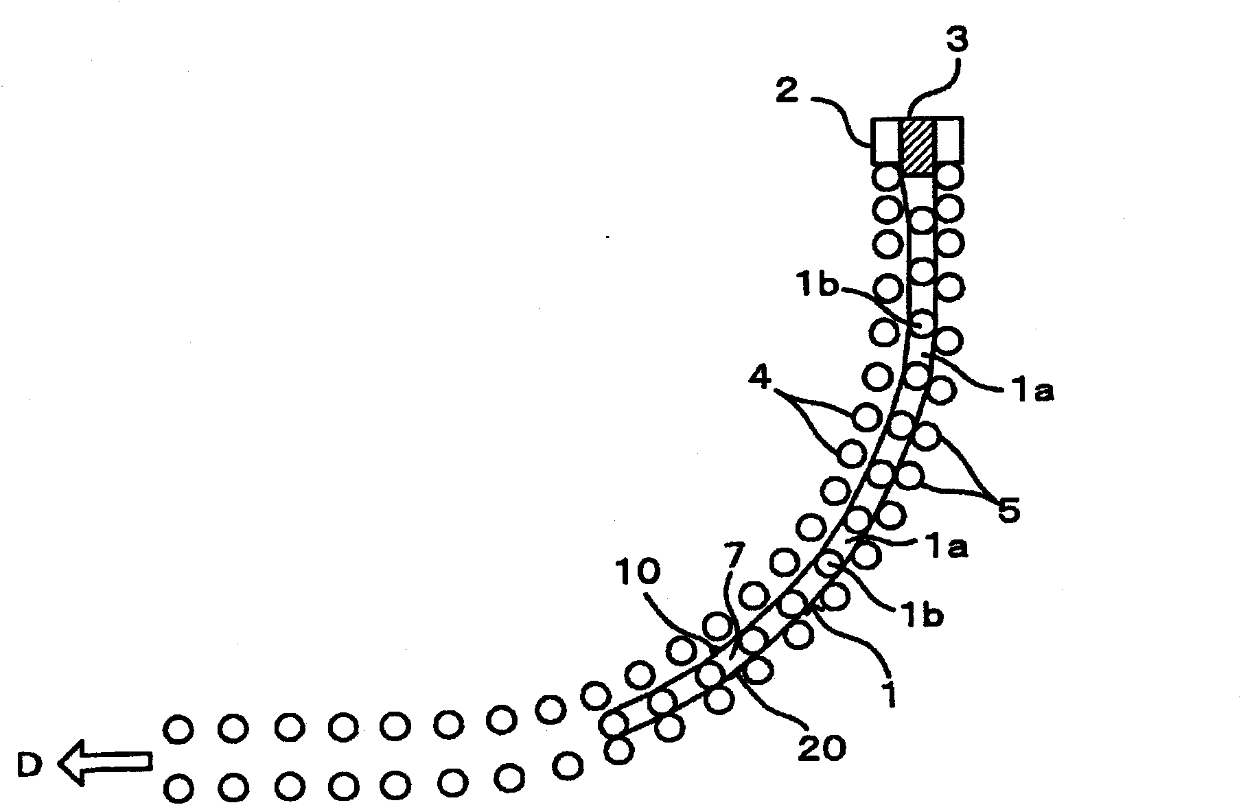
[0086] figure 1 It is a side view schematically showing the dummy bar 1 on which the roll gap measuring device according to this embodiment is mounted. The dummy bar 1 has a plurality of link members 1a and a shaft 1b, and guides molten steel 3 cast from a tundish not shown through a mold 2 so that it passes through a slab passage formed between a plurality of rollers 4 and 5. move within.

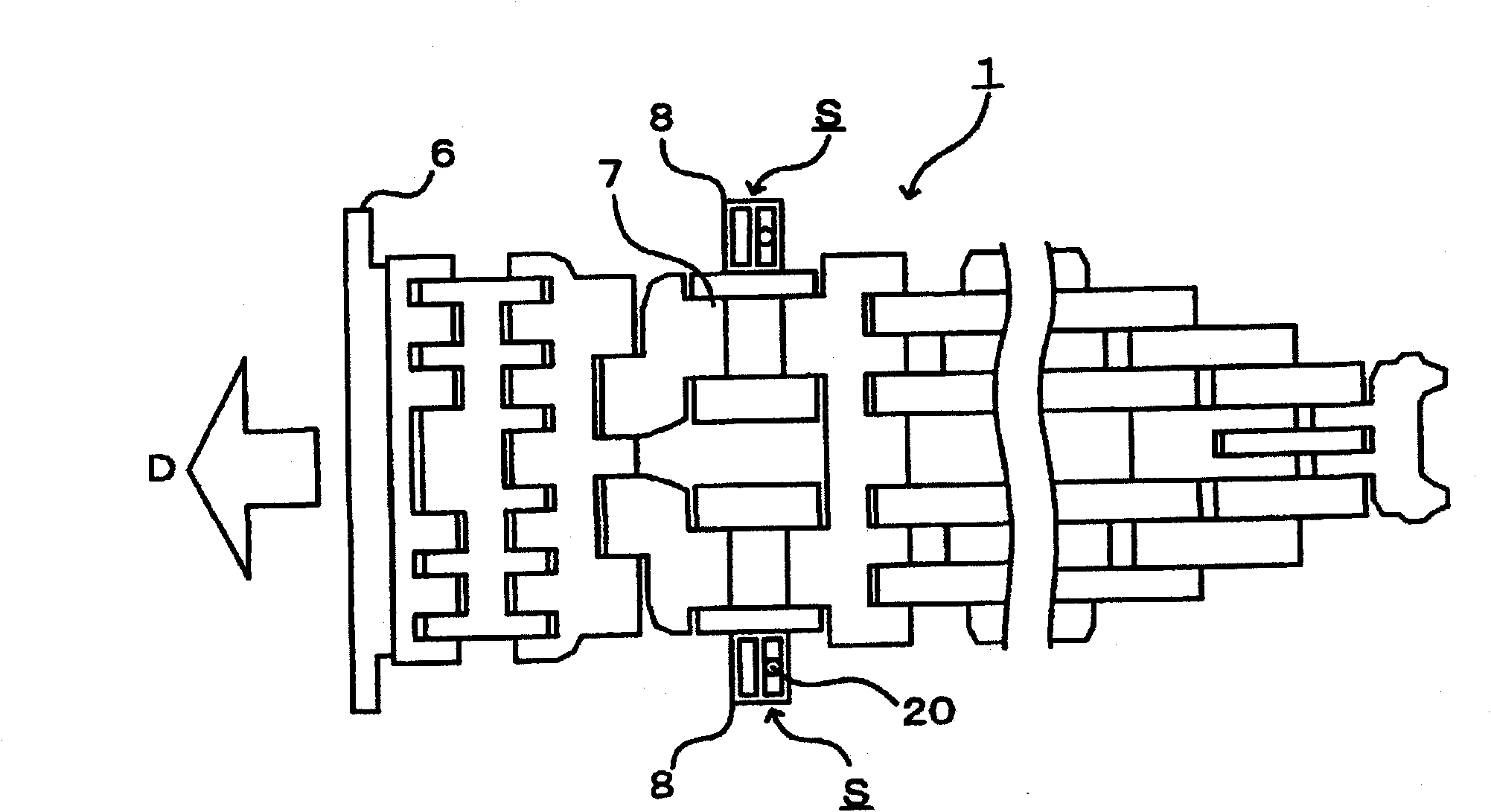
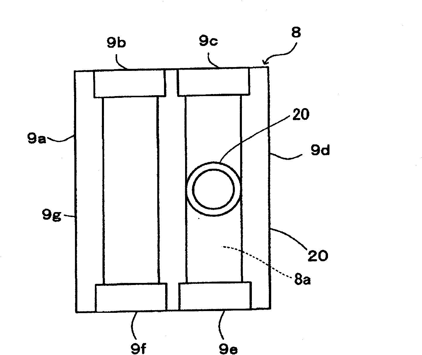
[0087] figure 2 The bottom surface of the dummy bar 1 on which the above-mentioned roll gap measuring device is mounted is shown. In the present embodiment, a pair of sensor blocks 8 provided near both ends in the width direction of the sensor link 7 disposed on the dummy bar head 6 side of the dummy bar 1, that is, on the front side in the conveying direction of the continuous casting machine, Respectively, be provided with the roller interval measuring device S (in figure 2 The illustration of...


PUM


Abstract

A roll-to-roll distance measuring device comprises a sensor device for measuring the distance between at least a pair of rolls disposed oppositely to each other on both sides of a cast piece passage in a continuous casting machine.  The sensor device comprises a movable sensor head having a cylindrical body part, a head part which is arranged continuously with the upper end of the body part in a conical shape and the top of which is convexed toward the upper roll among the pair of rolls; and a cylindrical sensor housing for storing the sensor head.  A reception part serving as a space for receiving foreign matters is formed between the bottom end outer peripheral surface of the head part and the upper end inner peripheral surface of the sensor housing when the bottom end of the head part is intruded into the sensor housing.  The bottom part of the reception part is formed in an annular flat surface in the top plan view thereof.

Description

technical field [0001] The present invention relates to a roll gap measuring device for measuring the gap between roll pairs of a continuous casting machine. [0002] This application claims priority based on Japanese Patent Application No. 2008-130461 for which it applied in Japan on May 19, 2008, and uses the content here. Background technique [0003] The continuous casting machine includes a plurality of roll pairs (guide rolls) arranged along the slab passage. The slab passes through the slab passage while being guided by these roller pairs. However, if an abnormality occurs in the gap between the pair of rolls, there is a possibility of bringing about quality degradation such as center segregation and internal fracture of the cast slab. Therefore, it is important to properly maintain the distance between the roller pairs, and for this reason, conventionally, the distance between the roller pairs has been measured. [0004] In the roll gap measurement of the continuo...

Claims


Application Information

Patent Timeline
Patent Type & Authority Patents(China)
IPC IPC(8): B22D11/16B22D11/08
CPCB22D11/08G01B5/16G01B11/026
Inventor 丸木保雄山条悟岩崎润哉矢野孝幸西原隆白神孝之全在荣许志行朴圭喆
Owner NIPPON STEEL CORP
Why Eureka
Eureka Blog
Learn More