
Interlocking device of high-tension switch gear

A technology of interlocking device and high-voltage switch, applied in switchgear, pull-out switch cabinet, electrical components, etc., can solve the problems of cumbersome installation, difficult processing of parts, difficult adjustment, etc. The effect of closing the circuit breaker

Active Publication Date: 2011-04-20
ANHUI ZHONGDIAN XINGFA & XINLONG TECH CO LTD
View PDF6 Cites 3 Cited by
  • Summary
  • Abstract
  • Description
  • Claims
  • Application Information

AI Technical Summary

Problems solved by technology

Since the connection between the locking device and the circuit breaker mechanism is a hard connection, the connecting device must pass through the small hole on the side plate of the handcart before it can be connected to the opening catch on the operating mechanism. Therefore, the positioning of the handcart and the spring mechanism or The positioning of the electromagnetic mechanism must be accurate, which undoubtedly increases the difficulty of manufacturing the cabinet and handcart
2: The mechanical locking device is installed on the cabinet body, and the operating mechanism is installed on the frame. Therefore, the turning handle of the mechanical locking device to the operating mechanism of the circuit breaker has to go through multiple transfers and positioning, and the number of connecting parts is large, and the parts are difficult Processing and installation are cumbersome, difficult to adjust, poor reliability

Method used


Image

  • Interlocking device of high-tension switch gear
  • Interlocking device of high-tension switch gear
  • Interlocking device of high-tension switch gear

Examples


Embodiment Construction

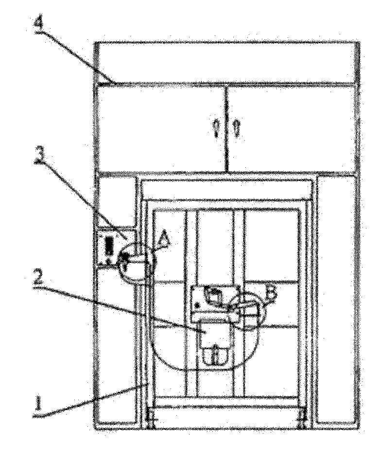
[0017] Such as Figure 1-3 As shown, a high-voltage switchgear interlocking device includes a handcart frame 1, an electromagnetic mechanism 2 and a mechanical locking device 3 arranged on the handcart frame 1, and the electromagnetic mechanism dead center round pin 17 of the electromagnetic mechanism 2 It is connected with the throttle cable 9 through a lever mechanism, and the throttle cable 9 is connected with the mechanical locking device 3 through a rotating mechanism.

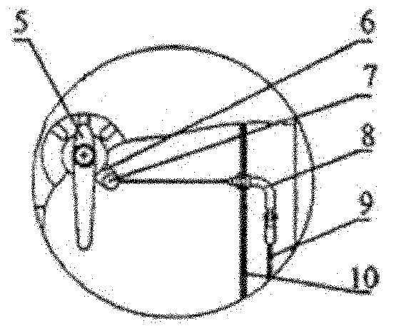
[0018] The turning mechanism includes a handle 5, a crank arm 6, and an upper joint 8; the handle 5 is connected to the mechanical locking device 3, and the handle 5 is provided with a crank arm 6, and the crank arm 6 Connect with the upper joint 8 through the throttle cable 9.

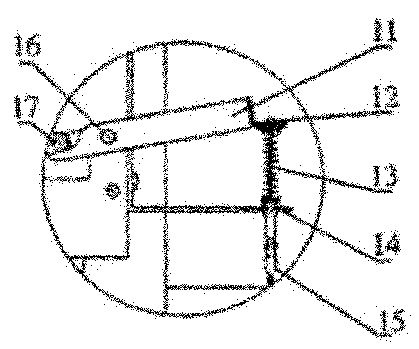
[0019] Described lever mechanism comprises lever 11, pressing plate 12, spring 13, lower joint 15; One end of described lever 11 is connected with electromagnetic mechanism 2 through electromagnetic mechanism dead center round p...


PUM


Abstract

The invention provides an interlocking device of a high-tension switch gear. The interlocking device comprises a lorry frame, an electromagnetic mechanism and a mechanical locking device, wherein the electromagnetic mechanism and the mechanical locking device are arranged on the lorry frame; the electromagnetic mechanism dead point round pin of the electromagnetic mechanism is connected with a cable accelerator through a lever mechanism; and the cable accelerator is connected with the mechanical locking device through a rotating mechanism. Compared with the prior art, the interlocking device provided by the invention has the advantages that the structure is simple, and the manufacturing is convenient; by rotating a handle to a segmentationally locked position, a crank arm on a handle shaft simultaneously rotates clockwise; the cable accelerator drives a lower adaptor to move down, a spring is compressed, a pressing sheet moves downwards, the larger end of a lever moves downwards, the smaller end of the lever moves up and pushes a mechanism dead point shaft to pass through a dead point, thus brake separating operation is completed under the action of a brake separating spring of a circuit breaker, thereby forcibly disconnecting the circuit breaker and realizing a function of preventing on-load disconnecting link; since the lever props the mechanism dead point all the time, the mechanism can not store energy and further can not switch in the circuit breaker, thereby realizing the function of preventing mistakenly switch in the circuit breaker; and the interlocking device is safe and reliable.

Description

technical field [0001] The invention relates to a high-voltage switchgear interlocking device. Background technique [0002] At present, there are two types of high-voltage switchgear produced and used in my country: handcart cabinets and fixed cabinets. The fixed cabinet is widely used because of its simple structure, low process requirements, cheap price and convenient operation, especially it does not require large operations. The use of space is one of the main high-voltage cabinet types used in combined box-type substations. Whether the fixed switchgear is equipped with an electromagnetic operating mechanism or a spring operating mechanism, all box-type switchgear mechanical locking devices are used. The device adopts the mandatory mechanical locking method, which has the characteristics of easy operation, safety and reliability, and fully meets the functional requirements of the "five defenses" of the complete set of equipment. The adjustment is also very convenient, ...

Claims


Application Information

Patent Timeline
Patent Type & Authority Applications(China)
IPC IPC(8): H02B11/133
Inventor 束龙胜宛玉超李开明孟祥军付强
Owner ANHUI ZHONGDIAN XINGFA & XINLONG TECH CO LTD
Learn More