
Mask defect testing apparatus

A defect detection and masking technology, applied in measurement devices, optical testing flaws/defects, semiconductor/solid-state device testing/measurement, etc., can solve problems such as inability to accurately and stably detect metal mask defects and limitations

Inactive Publication Date: 2011-04-20
SAMSUNG DISPLAY CO LTD
View PDF5 Cites 11 Cited by
  • Summary
  • Abstract
  • Description
  • Claims
  • Application Information

AI Technical Summary

Problems solved by technology

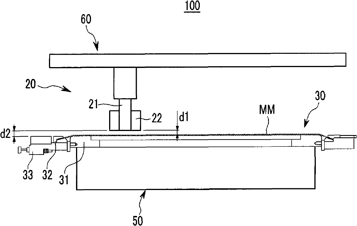
[0004] However, since the holder of the jig that fixes the edge of the metal mask generally has an upwardly protruding structure, the inspection camera can only approach the metal mask fixed on the jig within a range that does not collide with the jig.
In other words, due to the above structure of the jig for fixing the metal mask, the access of the camera to the metal mask to be inspected or the edge portion of the inspected metal mask is limited
Therefore, the presence of metal mask defects cannot be accurately and stably detected

Method used


Image

  • Mask defect testing apparatus
  • Mask defect testing apparatus
  • Mask defect testing apparatus

Examples


Embodiment Construction

[0023] Reference will now be made in detail to embodiments of the invention, examples of which are illustrated in the accompanying drawings, wherein like reference numerals refer to like elements throughout. The embodiments are described below in order to explain the present invention by referring to the figures.

[0024] In addition, since the size and thickness of constituent members shown in the drawings are arbitrarily given for better understanding and ease of description, aspects of the present invention are not limited to the illustrated size and thickness. In the drawings, the thicknesses of layers, regions, etc. are exaggerated for clarity and easy understanding. It will be understood that when an element such as a layer, film, region, or substrate is referred to as being "on" another element, it can be directly on the other element or be separated by intervening elements.

[0025] In the following, reference will be made to Figure 1-4 A mask defect inspection devi...


PUM

PropertyMeasurementUnit
bending angleaaaaaaaaaa
angleaaaaaaaaaa

Abstract

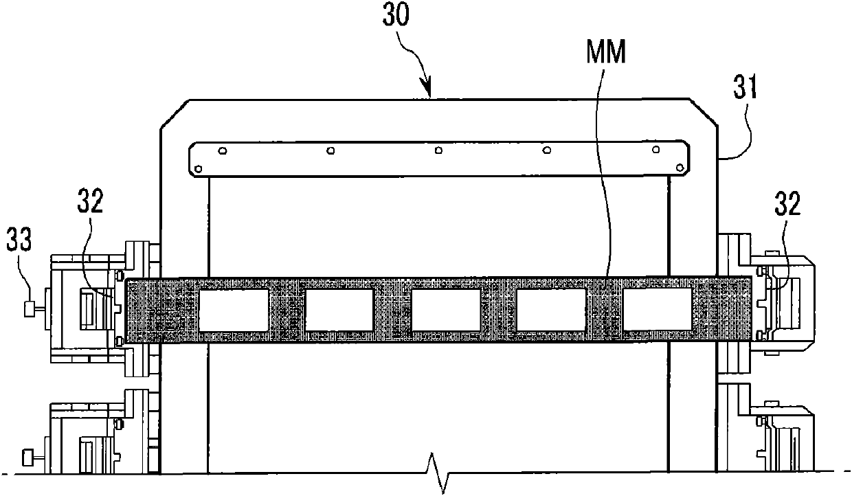
A mask defect test apparatus, including a tension jig unit having a supporter on which a metal mask to be tested is located, a clamp part disposed at both sides of the supporter to fix opposite edges of the metal mask, and a tension part to apply a tension force to the metal mask fixed by the clamp part; and a test unit to test the metal mask fixed by the tension jig unit. A vertical distance between the metal mask located on the supporter and the test unit is less than or equal to a vertical distance between the tension jig unit and the test unit.

Description

technical field [0001] Various aspects of the present invention generally relate to a mask defect inspection device, and more particularly, to a mask defect inspection device for detecting whether a mask used in a display panel manufacturing process is defective. Background technique [0002] Various types of masks are generally used in the display panel manufacturing process. For example, precision processes use metal masks. However, defects occur in some cases, such as fine foreign substances adhered to the metal mask to cause damage to the pattern of the mask. Using a metal mask with these defects will cause a lot of loss in the whole manufacturing process. [0003] Thus, the metal mask should be regularly inspected for the presence of defects before or after use of the metal mask. A method for detecting defects of a metal mask is to fix the metal mask to be detected on a jig, and then use a detection mask to detect defects of the fixed metal mask. At this time, the a...

Claims


Application Information

Patent Timeline
Patent Type & Authority Applications(China)
IPC IPC(8): G01N21/88G01N21/956
CPCG03F1/20G03F1/84H01L22/00
Inventor 朴时映
Owner SAMSUNG DISPLAY CO LTD
Learn More